Solder resist material, wiring board using the solder resist material, and semiconductor package

a solder resist and wired board technology, applied in the direction of solid-state devices, synthetic resin layered products, domestic applications, etc., can solve the problems of low accuracy of opening a pore through laser irradiation, crack generation, and reduced mounting area and package area, so as to reduce the size and weight of electronic devices, effectively suppress the warpage of the package, and high functionality

Inactive Publication Date: 2009-09-03
SUMITOMO BAKELITE CO LTD
View PDF12 Cites 27 Cited by
  • Summary
  • Abstract
  • Description
  • Claims
  • Application Information

AI Technical Summary

Benefits of technology

[0006]Under the above-described circumstances, in order to meet the demand for reduction in size and weight of electronic devices and their high functionality, solder resist materials, which can effectively suppress the warpage of a package even

Problems solved by technology

For this reason, there is a dilemma in that, though the number of wiring pins of an integrated circuit is more increased compared to that of a conventional semiconductor package, a mounting area and a package area are decreased.
However, when using a conventional photosensitive resin for a solder resist in which a pore is opened by means of laser irradiation, since a thermosetting resi

Method used


Image

  • Solder resist material, wiring board using the solder resist material, and semiconductor package
  • Solder resist material, wiring board using the solder resist material, and semiconductor package
  • Solder resist material, wiring board using the solder resist material, and semiconductor package

Examples


example 1

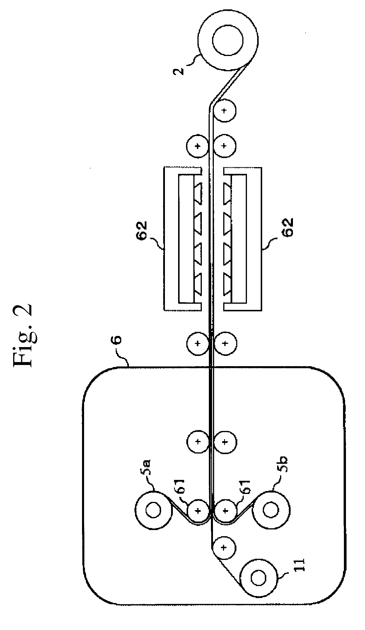
[0124]25 parts by weight of cyanate resin, 25 parts by weight of epoxy resin A, 10 parts by weight of phenoxy resin A, and 0.4 parts by weight of curing catalyst A were dissolved and dispersed in methyl ethyl ketone. To the mixture, 39 parts by weight of inorganic filler, 0.2 parts by weight of coupling agent, and 0.4 parts by weight of coloring agent were further added, and the obtained mixture was stirred for 10 minutes using a high-speed stirring apparatus to prepare a resin composition varnish 1 having the solid content of 50 wt %. The obtained resin composition varnish 1 was applied to a PET film as a base material (application thickness: 10 μm). It was subjected to heat treatment at 150° C. for 10 minutes, the solvent was removed therefrom for solidification, and thus a resin composition was obtained.

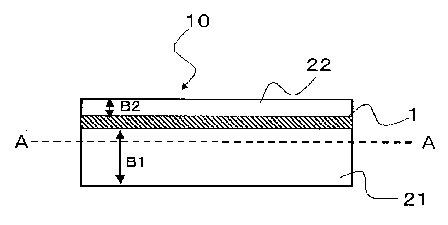
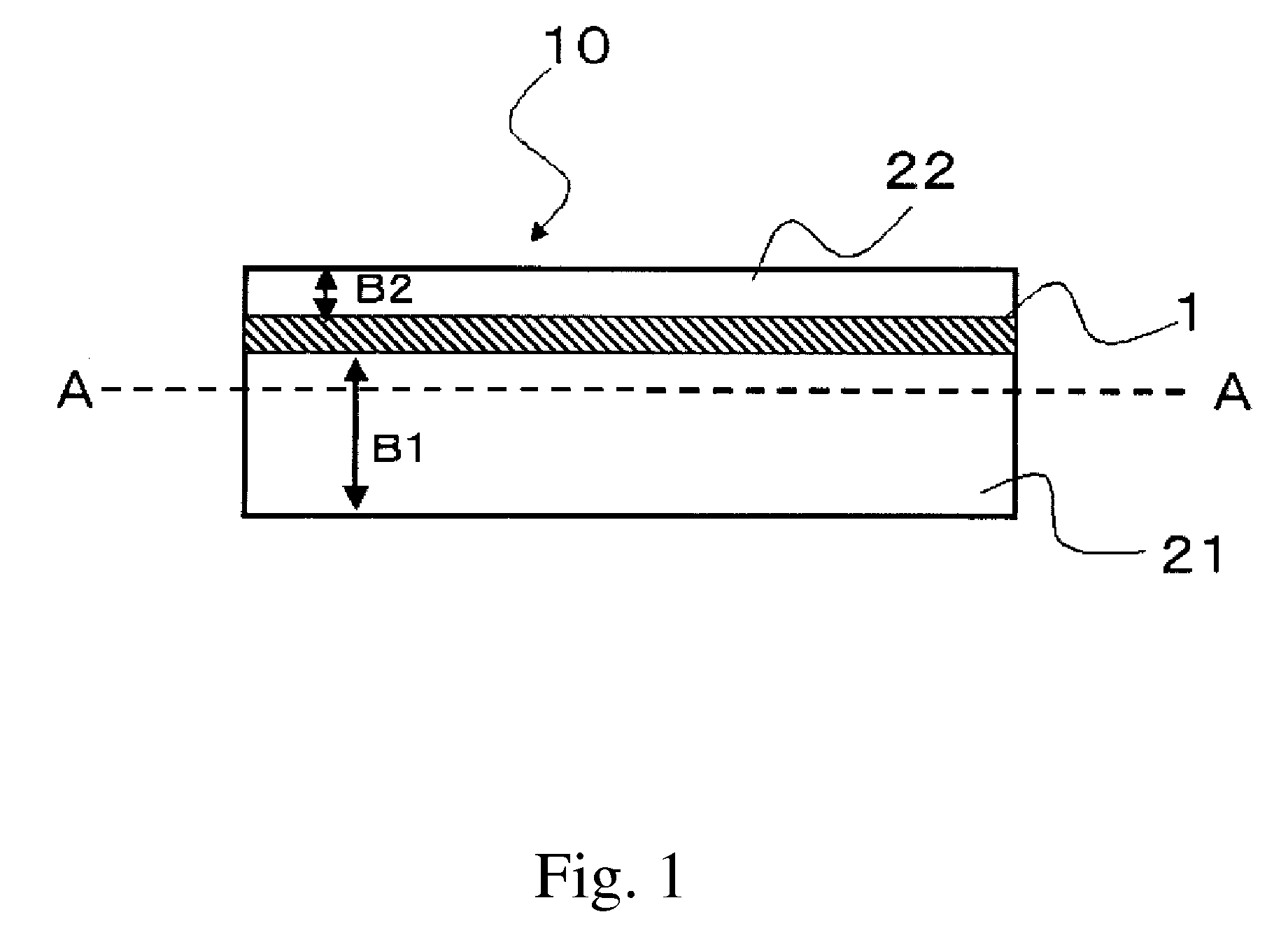
[0125]A glass nonwoven fabric (average fiber diameter: 7 μm, maximum fiber length: 10 mm, thickness: 14 μm, basis weight: 15 g / m2, EPC4015 manufactured by Japan Vilene Company), w...

example 2

[0126]15 parts by weight of cyanate resin A, 10 parts by weight of cyanate resin B, 25 parts by weight of epoxy resin A, 10 parts by weight of phenoxy resin A, and 0.4 parts by weight of curing catalyst A were dissolved and dispersed in methyl ethyl ketone. To the mixture, 39 parts by weight of inorganic filler, 0.2 parts by weight of coupling agent, and 0.4 parts by weight of coloring agent were further added, and the obtained mixture was stirred for 10 minutes using the high-speed stirring apparatus to prepare a resin composition varnish 2 having the solid content of 50 wt %. A solder resist material was obtained in a manner similar to that in Example 1 except for the above-described process, and evaluation thereof was made.

example 3

[0127]30 parts by weight of cyanate resin A, 15 parts by weight of epoxy resin A, 10 parts by weight of phenoxy resin A, 5 parts by weight of phenoxy resin B, and 0.4 parts by weight of curing catalyst A were dissolved and dispersed in methyl ethyl ketone. To the mixture, 39 parts by weight of inorganic filler, 0.2 parts by weight of coupling agent and 0.4 parts by weight of coloring agent were further added, and the obtained mixture was stirred for 10 minutes using the high-speed stirring apparatus to prepare a resin composition varnish 3 having the solid content of 50 wt %. A solder resist material was obtained in a manner similar to that in Example 1 except that the resin composition varnish 1 used in Example 1 was replaced by the resin composition varnish 3, and evaluation thereof was made.


PUM

PropertyMeasurementUnit
Fractionaaaaaaaaaa
Fractionaaaaaaaaaa
Lengthaaaaaaaaaa

Abstract

The present invention provides a solder resist material, which can suppress the warpage of a semiconductor package upon exposure to heat or impact even when used in a thin wiring board and meets a demand for size reduction in electronic devices and a higher level of integration, and a wiring board comprising the solder resist material and a semiconductor package. The solder resist material of the present invention can effectively suppress the warpage of a semiconductor package through a fiber base material-containing layer interposed between resin layers. The fiber base material-containing layer is preferably unevenly distributed in the thickness direction of the solder resist material.

Description

TECHNICAL FIELD[0001]The present invention relates to a solder resist material, a wiring board using the same and a semiconductor package.BACKGROUND ART[0002]Recently, reduction in size and weight of electronic devices and their high functionality have been rapidly improved. Size reduction and higher level of integration of semiconductor integrated circuits used in such electronic devices have also been improved. For this reason, there is a dilemma in that, though the number of wiring pins of an integrated circuit is more increased compared to that of a conventional semiconductor package, a mounting area and a package area are decreased. Under such circumstances, packaging methods having a high package density, such as BGA (Ball Grid Array) method and CSP (Chip Scale Package) method, which are different from conventional package methods, have been proposed.[0003]In these semiconductor package methods, instead of a lead frame used for conventional semiconductor packages, a wiring boa...

Claims


Application Information

Patent Timeline
IPC IPC(8): H01L23/52H05K1/02B32B9/04B32B3/00B32B7/02B32B17/10B32B27/38
CPCB32B27/12Y10T428/24612C08L63/00C08L65/00C08L71/00H05K1/0269H05K3/281H05K2201/0191H05K2201/0195H05K2203/161C08G2650/56Y10T428/2495C08L2666/14B32B3/263B32B5/022B32B5/024B32B27/10B32B27/18B32B27/20B32B27/28B32B27/38B32B2260/021B32B2260/028B32B2260/046B32B2262/0238B32B2262/0246B32B2262/0253B32B2262/0261B32B2262/0276B32B2262/0292B32B2262/101B32B2307/30B32B2307/306B32B2307/3065B32B2307/308B32B2307/402B32B2307/50B32B2307/718B32B2457/08Y10T428/31504Y10T428/31511Y10T428/31525C08G59/50C08J5/08C08L61/14
Inventor NAKAMURA, KENSUKEHIROSE, HIROSHI
Owner SUMITOMO BAKELITE CO LTD
Why Eureka
Try Eureka