
Harvesting hydrocarbons and water from methane hydrate deposits and shale seams

a technology of methane hydrate and hydrocarbons, which is applied in the direction of separation process, insulation, and wellbore/well accessories, etc., can solve the problems of bringing contaminants, increasing the hydrate component of the material, and difficult extraction, so as to reduce the oxygen level and reduce the temperature of the extraction zone

Inactive Publication Date: 2010-01-14
AIR WARS DEFENSE
View PDF2 Cites 71 Cited by
  • Summary
  • Abstract
  • Description
  • Claims
  • Application Information

AI Technical Summary

Benefits of technology

"The patent describes a method for extracting fuel gas and water from Methane hydrate deposits using a drilling process. The method involves using pure Nitrogen gas as a carrier to prevent fires and lower Oxygen levels. The drilling process involves using a hammer drill with pneumatic retraction to pull organics and fresh water from the deposit. The extracted materials are then separated and can be stored and sold for use as refined heating gases. The method also includes using Liquid Nitrogen as a fire suppressant carrier and to protect the extraction zone from sea water or Methane hydrate release. The method expands the field of extraction by drilling narrow peripheral holes and converting them to supplemental heating locations to keep the water and heating gases gaseous and moving to the main drilling. The full system includes a series of ring supported expandable tubes to carry the evaporants from the periphery to the extraction drilling."

Problems solved by technology

. . ane molecule and it accumulates forming a very impermeable white “burnable ice.” It is often found in clay deposits making the extraction more difficult, though some is in sand deposits.
The water adds to the hydrate component of the material and can bring contaminants.

Method used


Image

  • Harvesting hydrocarbons and water from methane hydrate deposits and shale seams
  • Harvesting hydrocarbons and water from methane hydrate deposits and shale seams
  • Harvesting hydrocarbons and water from methane hydrate deposits and shale seams

Examples


Embodiment Construction

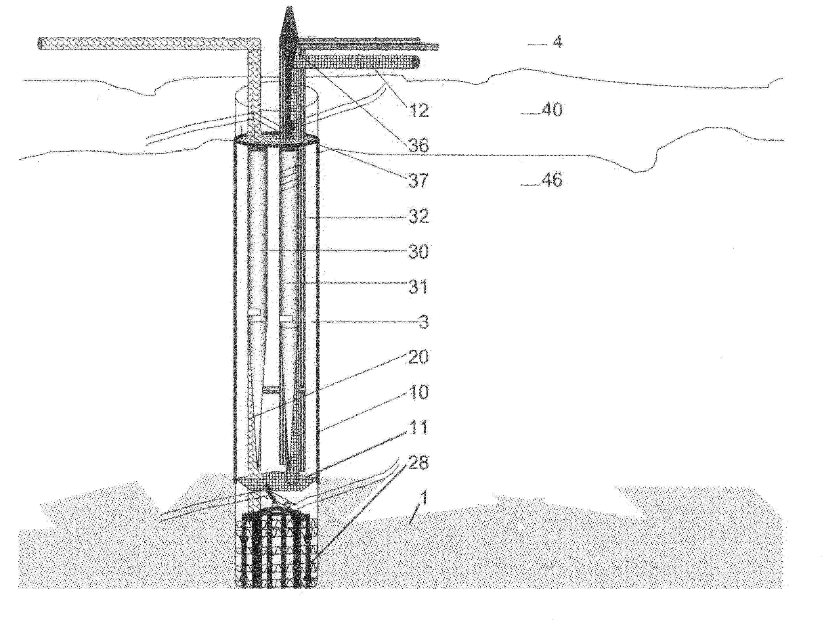
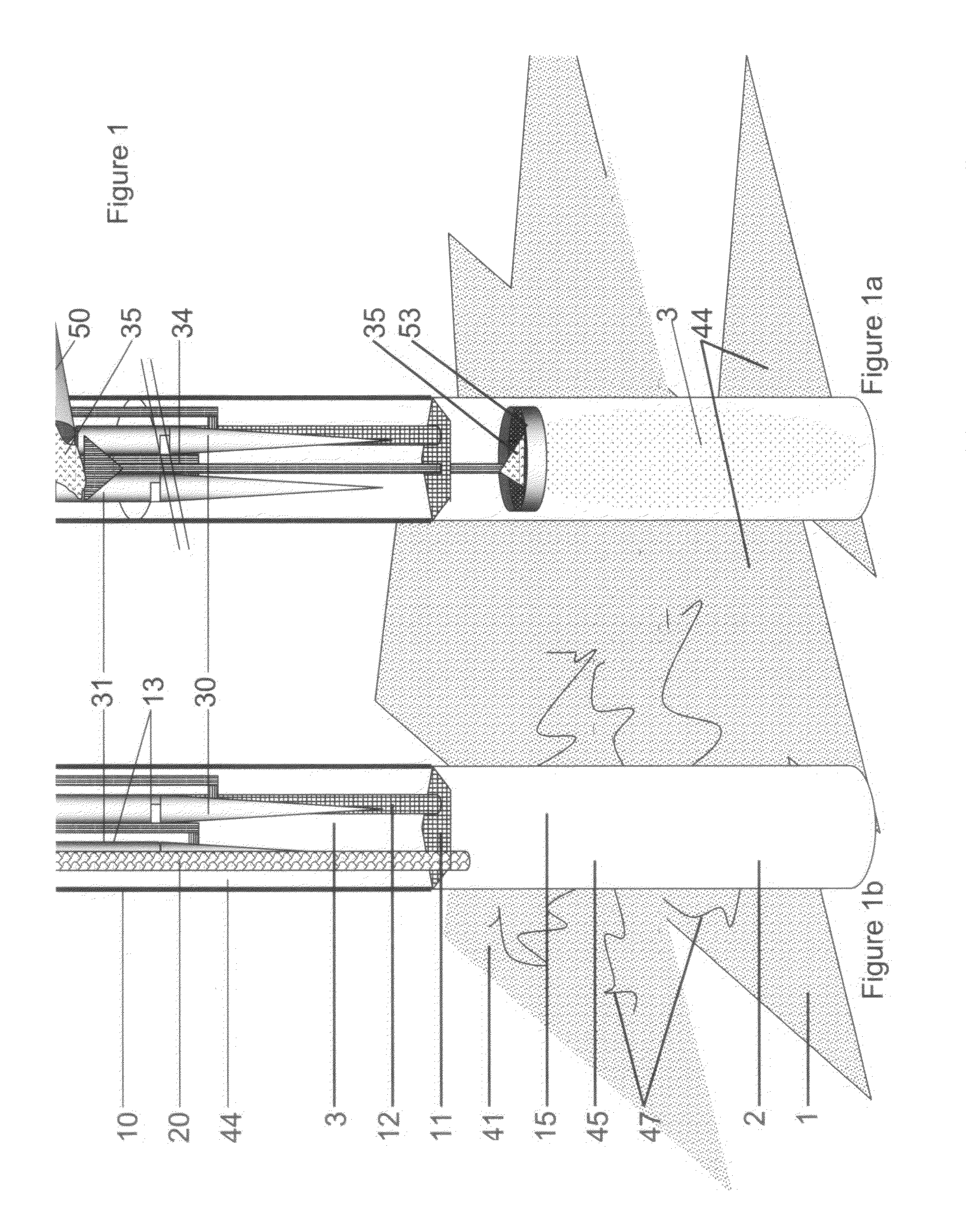
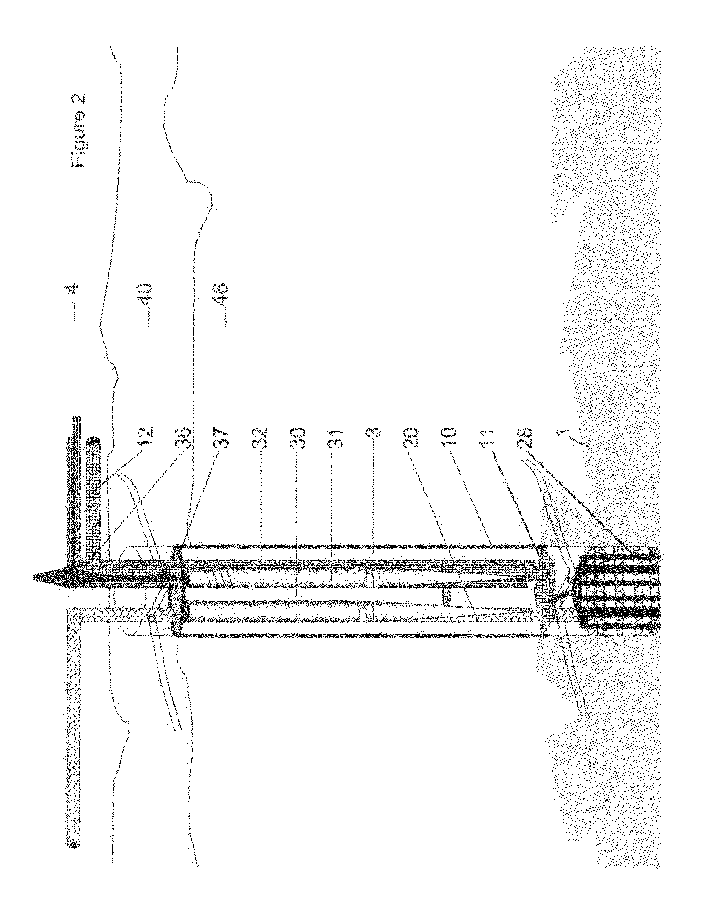
[0065]Turning now to the drawings and initially to FIGS. 1-2, showing the center, lower section and top of the drill hole for extracting fuel hydrocarbons from Methane hydrate. In FIG. 1, the Methane hydrate deposit 1 is cooled with evaporating Liquid Nitrogen to brittle cold in FIG. 1a, and then vibrated with sound at both the frequency of the standard organ pipe 30 and the frequency difference beats created by the adjustable frequency organ pipe 31 that can vary widely with the tuning of the adjustable pipe in FIG. 1b. The purpose of this ground stimulation is break up the seam structure when brittle cold, and then continued through the heating phase FIG. 2 to get air throughout the deposit 1 such that the heat evaporated Methane and water escape the structure of the deposit. If the initial cold separates Methane from water, the water will freeze providing the ice encirclement and the Methane will be drawn with the Nitrogen.

[0066]FIG. 1 shows both the preparatory cryogenic freezin...


PUM

PropertyMeasurementUnit
boiling pointaaaaaaaaaa
depthsaaaaaaaaaa
depthaaaaaaaaaa

Abstract

A method of extraction of fuels, organic pollutants, and elements from Methane hydrate deposits, shale seams and the soil is described which freezes the zone and heats the center carrying the fuel, chemicals and water in these deposits and seams from where they are found, be it deep in the sea or on land, and carries them into the condensing unit in inert Nitrogen gas. Required drilling on the surface or sea bottom includes a main shaft and with auxiliary narrow drillings widely spaced from the shaft. The extraction zone, which is first cooled to brittle cold using the evaporation of Liquid Nitrogen and fractured with vibrations, is heated to the highest temperature of the hydrocarbon fraction desired to be extracted. The evaporating hydrocarbons are extracted in a Nitrogen gas carrier, a recognized fire suppressant (NFPA Code 2000). To speed the extraction rate, tonal input from two or more sounding units vibrates the seam structure freeing the evaporated hydrocarbons allowing more rapid escape into the shaft. To prevent air loss in aquifers, ice barriers seal the zone periphery. These hydrocarbons are separated into the hydrocarbons fractions, into fuel fractions as heating oil, kerosene, gasoline, ethers, and fuel gas including methane, Argon / Oxygen and rare gas segments, or, if pollutants, into the separate chemicals by boiling point. The thermal gradient of the extraction pipe is implemented by sourcing the Nitrogen from Liquid Nitrogen and bundling those pipes with the extraction pipe condensing its contents by hydrocarbon fractions into vessels and gas drums depending on boiling points of fractions. Water is separated from the gasoline segment and purified first by separation and then by freezing. The extraction of deep deposits layer the extraction zones as well as work neighboring extraction zones covering many acres. Fuel gases can be liquefied or burned in an on-site electric generating plant.

Description

BACKGROUND OF THE INVENTION[0001]1. Field of the Invention[0002]Like the world's coal and shale. reserves which often pose difficulty in harvesting the fuel components, harvesting the light fuel gases and the fresh, distilled water from Methane Hydrate deposits needs a workable tool. Extraction using a modification of the equipment described in the U.S. patent application Ser. No. 11 / 903,346 can bring the fuels and water to locations where it will be useful. And, because fuel, Methane with minor amounts of Butane and Propane, could be used at the platform over the deep extraction process to produce electricity an electric power generating plant can be located at the extraction site. The electric power can be carried to land in a huge insulated cable(s) along side distilled water pipeline providing electricity and potable water to local populations. For concerns of Global Warming, the Carbon dioxide emission from burning the heating gases can be frozen as dry ice when in darkness and...

Claims


Application Information

Patent Timeline
Patent Type & Authority Applications(United States)
IPC IPC(8): E21B43/285B01D5/00
CPCB01D5/0009B01D5/0036B01D5/009B01D5/0093E21B2043/0115E21B28/00E21B36/00E21B43/24E21B43/34C10G2300/1029E21B41/0099
Inventor DUBRUCQ, DENYSE CLAIRE
Owner AIR WARS DEFENSE
Learn More