
Detection of vapor phase compounds by changes in physical properties of a liquid crystal

Inactive Publication Date: 2010-04-15
PLATYPUS TECH
View PDF99 Cites 23 Cited by
  • Summary
  • Abstract
  • Description
  • Claims
  • Application Information

AI Technical Summary

Benefits of technology

[0020]The present invention is not limited to the use of devices with particular types of surfaces. Indeed, the use of a variety of surface materials is contemplated, including, but not limited to gold, glass and silicon. In some embodiments, the surface (gold, glass or silicon) is functionalized by chemical treatment (for example by addition of a self-assembled monolayers or gold, silane treatment on glass or silicon). In some embodiments, the functionalized surface promotes wetting by liquid crystals. In some embodiments, the functionalized surface aligns mesogens. In some embodiments, the functionalized surface reduces the anchoring energy of the mesogens so that the interaction of the analyte with the LC composition facilitates reorientation of liquid crystals on the surface. In some embodiments, the functionalized surface repels the liquid crystal. In some embodiments, the surface functionalization chemistry is deposited such that delivery of the LC composition to the substrate results in a patterned distribution of areas wetted with the LC composition and areas void of the LC composition.
[0025]In some embodiments, a mixture of different mesogens in the LC composition is contemplated. In some embodiments, the mixture of mesogens increases the sensitivity of detection by methods including but not limited to improving the partition of target analytes, increasing the wetting property of the film of the LC composition, improving the interaction of analytes with the LC compositions or surface or enhancing the change in physical properties. In some embodiments, the phase transition is due to a physical dilution of the liquid crystal. The phase transition is not limited to any particular order of change. Indeed, a variety of phase changes are contemplated including a phase transition from a higher order to a lower order or vice versa. In some embodiments the thermotropic liquid crystal transitions include, but are not limited to an isotropic phase changing to a nematic phase, a smectic A phase changing to a nematic phase, and a nematic phase changing to an isotropic phase. The present invention is not limited to the use any particular mesogen. Indeed, the use of a variety of mesogens is contemplated, including, but not limited to MBBA, EBBA, MLC-6812, MLC 12200, 5CB (4-n-pentyl-4′-cyanobiphenyl), 8CB (4-cyano-4′octylbiphenyl) and 4-(trans-4-heptylcyclohexyl)-anilin. In some embodiments, the LC composition undergoes an orientational transition in the presence of said analyte selected from the group consisting of homeotropic changing to a planar alignment, random planar alignment changing to uniform planar alignment, uniform planar alignment changing to random planar alignment, and planar alignment changing to homeotropic alignment. In some embodiments, the LC composition undergoes an orientational transition followed by a phase transition in the presence of said analyte.

Problems solved by technology

Twenty-two million people in the US have been diagnosed with asthma (CDC, 2008), yet the tools available for monitoring asthma are limited.
However, abnormal readings from either of these devices can be attributed to a variety of causes other than asthma, and these techniques may not be predictive of onset of an acute asthmatic attack, nor provide immediate feedback on the effect of a therapeutic intervention.
While numerous studies have been performed to measure levels of exhaled NO there is little consensus on what the standard level is in healthy subjects.
However, some of the NO variability can be attributed to the variety of test methods due to the lack of standardized procedures among the testing groups (Müller et al, 2005).
One of the major problems in completing these assessments is the lack of methods and monitoring devices to measure components from exhaled breath.
The general deficiencies of such instruments are that they are prohibitively expensive and technically complicated, require recalibration, most lack portability, require GC for specificity, sensitive to humidity, and require on-board hydrogen gas.
In general these instruments have selectivity issues, high drift, and short shelf-life, require internal pump and elevated temperatures for operation, are sensitive to water vapor and to hydrogen.
They are prohibitively expensive, susceptible to humidity changes, and not readily transportable.
They have limited dynamic range, lack specificity, high rate of false positives, optics impaired by particulates, and sensitive to humidity.
In general, hurdles to these sensor technologies include instrumentation that is expensive, requires frequent calibrations and regular maintenance, complicated to operate, large in size, and lacks selectivity for the targeted gas.

Method used


Image

  • Detection of vapor phase compounds by changes in physical properties of a liquid crystal
  • Detection of vapor phase compounds by changes in physical properties of a liquid crystal
  • Detection of vapor phase compounds by changes in physical properties of a liquid crystal

Examples


example 1

Screening of LCs for Ability to Detect Nitric Acid Vapor

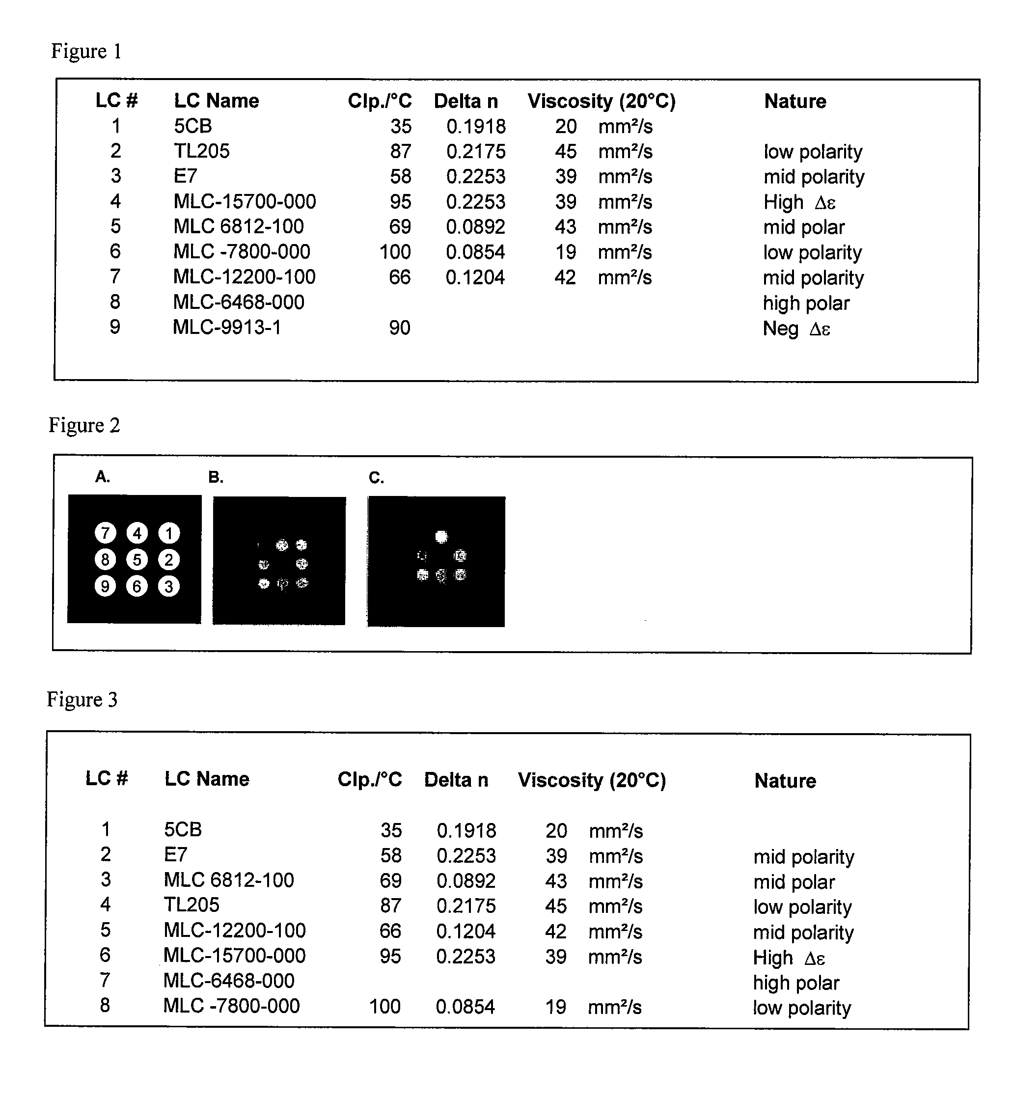
[0165]This example describes the identification of liquid crystals that can be used for detection of nitric acid vapor. The screen was performed by using a single substrate that contained a 3×3 array of micropillar features to aid in spreading and maintaining a thin film of liquid crystals, as shown in FIG. 2. The substrate was treated with titanium and gold. The substrates were prepared by depositing ultrathin (optically transparent) gold films onto glass substrate by electron beam deposition. Uniformly coated chips (100 Angstrom gold on a 20 Angstrom titanium adhesion layer) with micropillar features were spotted with ˜0.6 μl of 9 different liquid crystal candidates (FIG. 1). The sensor chip was placed into a petri dish and a 110 μl droplet of 70% aqueous solution of nitric acid (HNO3) was deposited proximal to the chip inside the dish. The dish was covered with a lid and the edges were sealed by wrapping with parafilm. This ...

example 2

Specificity of LCs for Detection of Nitric Acid Vapor

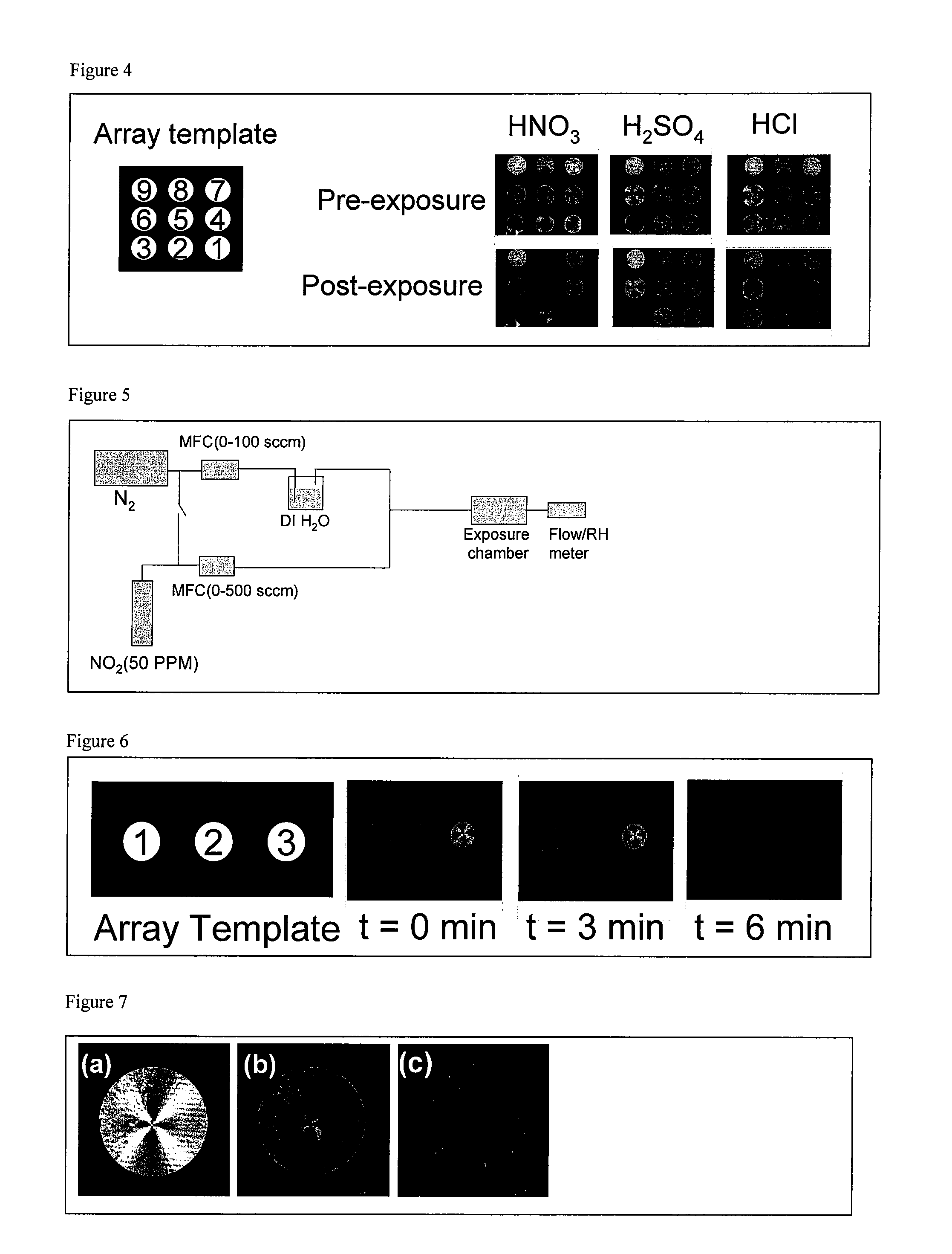
[0166]This example describes the specificity of 3 LCs for detection of nitric acid vapors. The screen was performed by using a single substrate that contained a 3×3 array of micropillar features, as shown in FIG. 4. The substrate was treated with titanium and gold. The substrates were prepared by depositing ultrathin (optically transparent) gold films onto a glass substrate by electron beam deposition. Uniformly coated chips (100 Angstrom gold on a 15 Angstrom titanium adhesion layer) with micropillar features were spotted with ˜0.6 μl of 9 different liquid crystal candidates (FIG. 3). The sensor chip was placed into a petri dish and a 110 μl aqueous solution of either nitric acid (HNO3, 70%), hydrochloric acid (HCl, 37%) or sulfuric acid (H2SO4, 70%) was deposited proximal to the chip inside the dish. The dish was covered with a lid and the edges were sealed by wrapping with parafilm. This exposure chamber was sandwiched between ...

example 3

Detection of Nitrogen Dioxide Using LC-Based Sensors

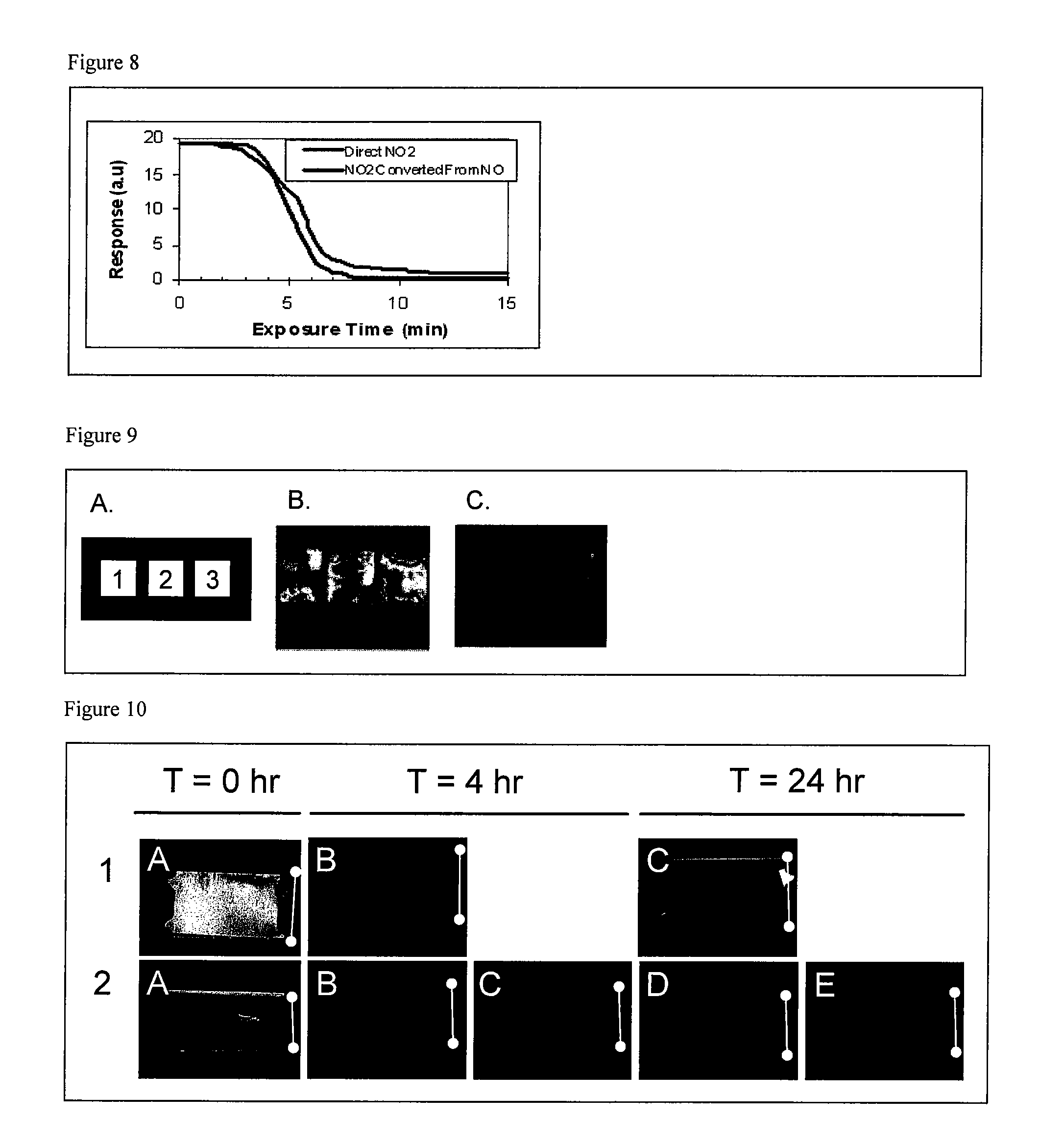
[0167]This example describes the conversion of nitrogen dioxide to nitric acid vapor and the subsequent detection by liquid crystals. Nitric acid vapor was generated by mixing nitrogen dioxide (NO2) gas at 50 ppm in nitrogen with moist nitrogen (N2) generated by bubbling through water. The rate of flow of each gas, i.e., NO2 and N2 (bubbled through water), was adjusted using mass flow controllers (0-100 sccm and 0-500 sccm) to achieve desired concentrations and then the gases were mixed together. The flow of the nitrogen dioxide and nitrogen bubbled through water was adjusted so that the total flow was 200 sccm. The relative humidity of the nitrogen bubbled through water was ˜96% and reduced to ˜80% after mixing with nitrogen dioxide. A diagram of the gas generation system and exposure set-up is provided in FIG. 5. The sensor consisted of a 1×3 array of three different liquid crystals (5CB, MLC 6812-000 and MLC 12200-100) that were...


PUM


Abstract

The present invention relates to the field of detection of components in gas phase, and in particular to detection of nitric oxide exhaled as a component of breath, using a liquid crystal assay format and a device utilizing liquid crystals as part of a reporting system.

Description

CROSS REFERENCE TO RELATED APPLICATIONS[0001]This application claims the benefit of U.S. Prov. Appl. No. 61 / 096,972 filed Sep. 15, 2008, the disclosure of which is incorporated herein by reference in its entirety.GOVERNMENT SUPPORT[0002]This invention was made in part with government support under DOD contract #W911SR-07-C-0061 and research grant R43ES016389 funded by the NIH / NIEHS. The Government has certain rights in the invention.FIELD OF THE INVENTION[0003]The present invention relates to the field of detection of different classes of compounds, and in particular to detection of vapor phase compounds using a liquid crystal (LC) assay format and a device utilizing liquid crystals as part of a reporting system.BACKGROUND OF THE INVENTION[0004]The type and concentration of synthetic chemicals that are in our environment today are of greater concern to government, businesses, and society in general than in any time in history. Multiple factors contribute to this, such as national se...

Claims


Application Information

Patent Timeline
IPC IPC(8): G01N31/00B01J10/00
CPCB82Y30/00G01N21/77G01N31/22G01N33/497Y10T436/184Y10T436/179228Y10T436/204165Y10T436/200833Y10T436/177692Y10T436/175383Y10T436/15Y10T436/178459Y10T436/202499Y10T436/182G01N33/0037Y02A50/20G01N33/4975G01N27/227
Inventor ACHARYA, BHARATSEN, AVIJITABBOTT, NICHOLASKUPCHO, KURT
Owner PLATYPUS TECH
Learn More