
Composite magnetic material for magnet and method for manufacturing such material

a magnetic material and magnet technology, applied in the field of rare earthironnitrogen based composite magnetic materials for magnets, can solve the problems of large obstacles to broader applications, low magnetic characteristics, loss, etc., and achieve the effect of high magnetic characteristics and high electrical resistivity

Inactive Publication Date: 2010-10-14
TOKYO INST OF TECH +1
View PDF6 Cites 39 Cited by
  • Summary
  • Abstract
  • Description
  • Claims
  • Application Information

AI Technical Summary

Benefits of technology

[0047]An R—Fe—N based magnetic material may contain as a sub-phase an R—Fe alloy raw material phase, a hydride phase, a decomposed phase or oxidized amorphous containing an Fe nanocrystal, or the like. However, the volume fraction thereof needs to be suppressed lower than the content of the main phase in order to sufficiently exhibit the advantage of the present invention, and it is very preferable in practical use that the content of the main phase exceeds 75% by volume with respect to the total of the R—Fe—N based magnetic material.

Problems solved by technology

Although metal magnet materials described above have recently been used for motors for driving cars, motors for air conditioners and the like from requirements for energy saving and space saving, since the metal based magnetic materials have low electrical resistivity, there actually arises a problem of loss due to eddy current generated in magnets.
Due to this eddy current loss, heat is generated in magnets to cause a temperature rise and thereby demagnetization in some cases, giving a large obstacle to broader applications.
However, since magnetic characteristics thereof are low, the oxide based magnet materials are unlikely to be used in recent year's devices, which are reduced in size and provide high performance.

Method used


Image

  • Composite magnetic material for magnet and method for manufacturing such material
  • Composite magnetic material for magnet and method for manufacturing such material
  • Composite magnetic material for magnet and method for manufacturing such material

Examples


example 1

[0175]Sm of 99.9% in purity and Fe of 99.9% in purity were melted and mixed in an arc melting furnace in an argon gas atmosphere to fabricate an ingot. The ingot was annealed in an argon atmosphere at 1,150° C. for 20 hours, slowly cooled, and subjected to a surface polishing to prepare an alloy having a composition of Sm10.6Fe89.4.

[0176]The alloy was pulverized by a jaw crusher, and then further pulverized by a cutter mill in an argon atmosphere, and the particle size was regulated by a sieve to obtain a powder of approximately 60 μm in average particle diameter. The Sm—Fe alloy powder was charged in a horizontal tubular furnace, and subjected to a heat treatment at 450° C. in a mixed gas flow having an ammonia partial pressure of 0.35 atm and a hydrogen gas partial pressure of 0.65 atm for 2 hours, and further annealed in an argon gas flow for 30 min to adjust the alloy powder to a SM9.0Fe76.1N14.9 composition of approximately 30 μm in average particle diameter.

[0177]Then, the mag...

example 2

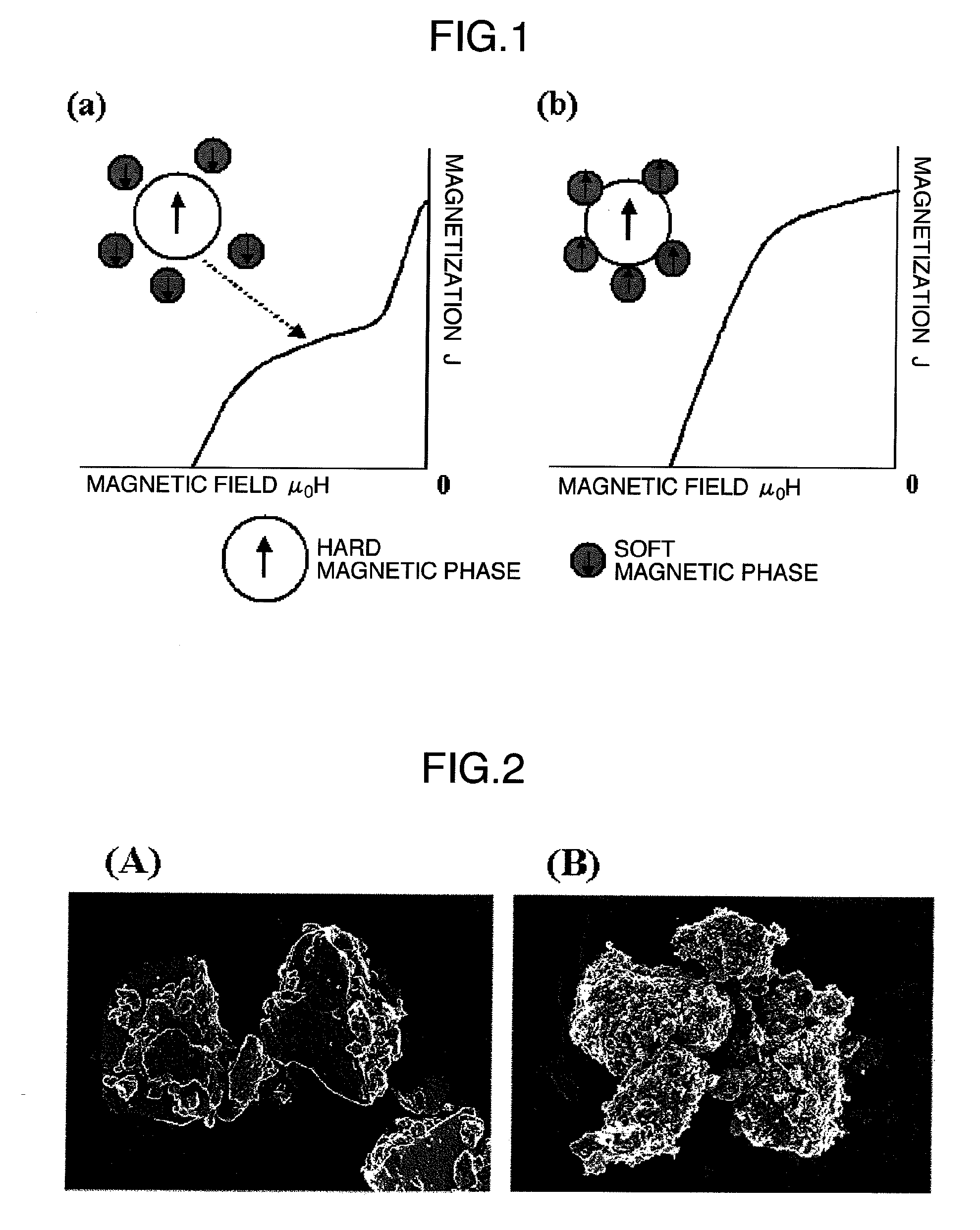
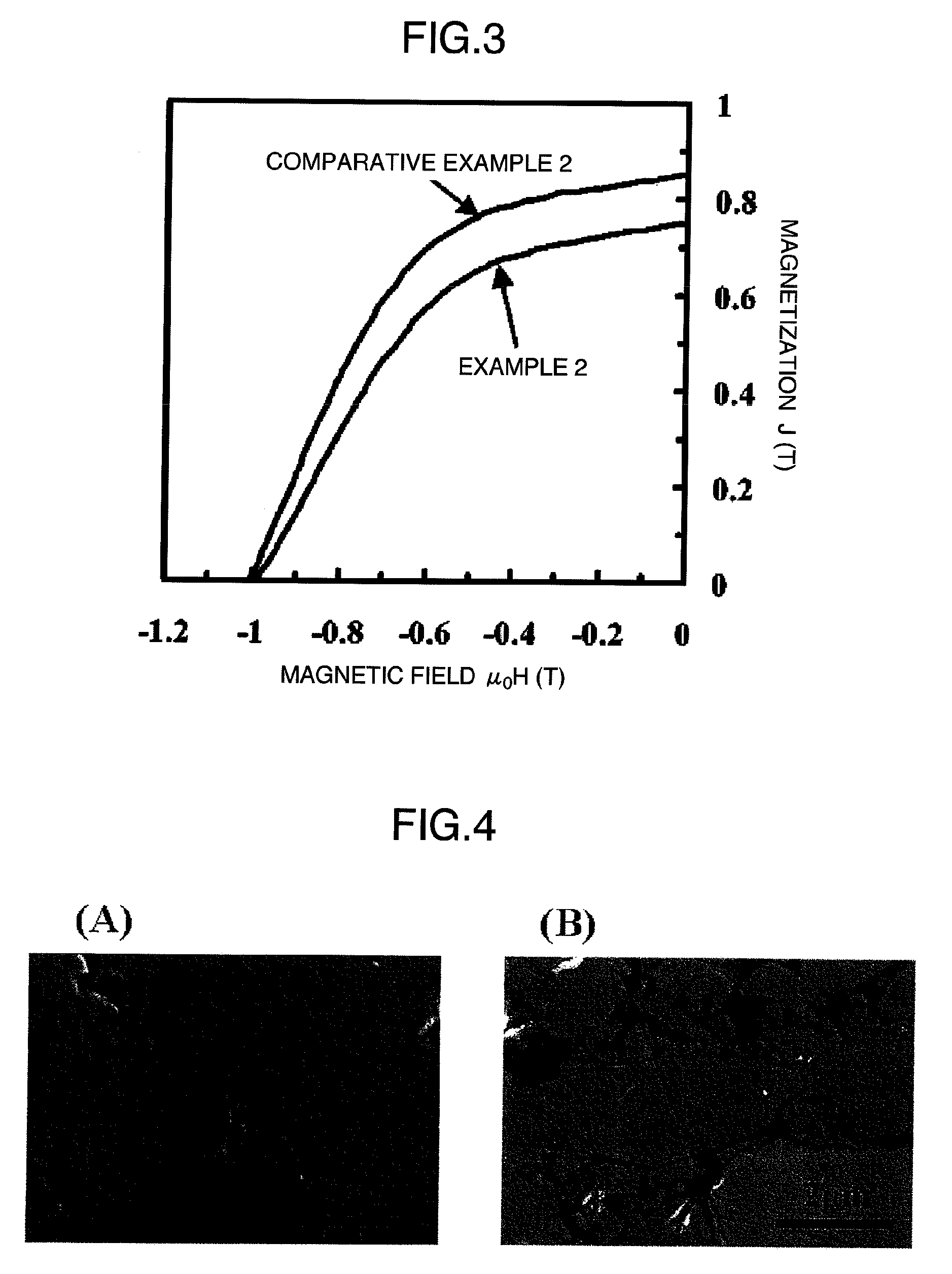
[0182]A rare earth-iron-nitrogen based magnetic material of a Sm9.1Fe77.3N13.6 composition having an average particle diameter of about 2 μm and a rhombohedral crystal structure was obtained as in Example 1. Then, the magnetic material powder was subjected to the same ferrite coating treatment as in Example 1, but under the altered condition where the reaction time was set at 20 min while the pH of the system was adjusted so as to gradually shift from an acidic side to an alkali side in the range of 4.6 to 13.8, to obtain a composite magnetic material for a magnet of a Sm7.5Fe71.6N11.3O9.6 composition. The SEM photographs of the composite magnetic material and the rare earth-iron-nitrogen based magnetic material before the ferrite coating treatment are shown in FIG. 2. (A) is a SEM photograph of the rare earth-iron-nitrogen based magnetic material powder before the ferrite coating treatment; and (B) is a SEM photograph of the composite magnetic material powder after the ferrite coat...

examples 5 to 7

[0210]Composite magnetic materials were obtained by the same method as in Example 1, except for altering the compositions of a rare earth-iron-nitrogen based magnetic material powder and a ferrite coating layer as shown in Table 2. The materials were powder-compacted at an external magnetic field of 1.5 T at an applied pressure of 1.2 GPa; and their magnetic characteristics and electrical resistivities were measured and the results as shown in Table 2 were obtained. The electrical resistivities in all of powder-compacted magnets of the composite magnetic materials exceeded 2,500 μΩcm, achieving the electrical insulation. In Table 2, the particle diameters of the rare earth-iron-nitrogen based magnetic material and the thicknesses of the ferrite coating layer are shown together. From the results of the X-ray diffractometry, it was revealed that all of these composite magnetic materials for a magnet had a rhombohedral crystal structure. The ferrites of the ferrite coating layers were ...


PUM

PropertyMeasurementUnit
thicknessaaaaaaaaaa
particle diameteraaaaaaaaaa
thicknessaaaaaaaaaa

Abstract

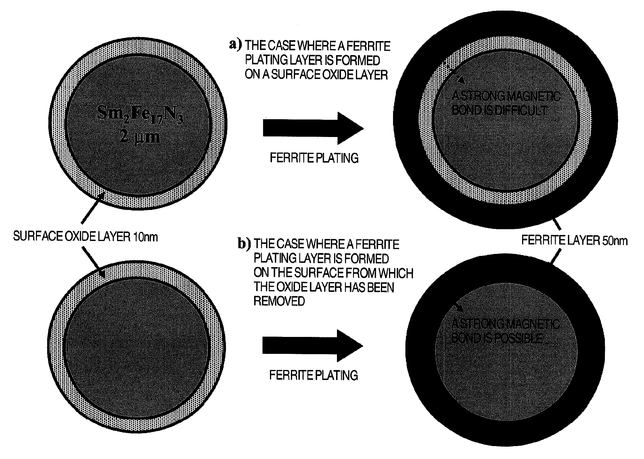
Provided is a composite magnetic material having high magnetic characteristics and high electrical resistivity to be used for a magnet, especially a composite magnetic material to be suitably used for a rotary motor magnet or the like which functions in a high frequency region. The composite magnetic material for the magnet is provided by covering the surface of a rare earth-iron-nitrogen based magnetic material with a ferrite based magnetic material.

Description

TECHNICAL FIELD[0001]The present invention relates to a rare earth-iron-nitrogen based composite magnetic material for a magnet having high magnetic characteristics and a high electrical resistivity, and excelling in oxidation-resistant performance.[0002]Composite magnetic materials for magnets are used for various types of actuators, voice coil motors, linear motors, rotors and stators of motors for rotary machines, magnetic field generating sources of medical apparatuses and metal sorting machines, magnetic field generating sources for analyzers such as VSM apparatuses, ESR apparatuses and accelerators, magnetron traveling wave tubes, OA devices such as printer heads and optical pickups, undulators, wigglers, retarders, magnet rolls, magnet chucks, various types of magnet sheets and the like. They are utilized especially for motors and electric generators whose rotation speed exceeds 500 rpm for driving cars such as electric cars, fuel cell cars and hybrid cars; machine tools; ele...

Claims


Application Information

Patent Timeline
Patent Type & Authority Applications(United States)
IPC IPC(8): G11B5/62B05D3/00B05D5/00B22F1/16
CPCB22F1/02B22F2009/041H01F41/0266H01F1/09H01F1/059H01F1/0579B22F2009/043B22F2009/046B22F2998/10C22C33/0278C22C2202/02C23C8/10C23C30/00B22F9/04B22F1/0088B22F3/02B22F1/16
Inventor IMAOKA, NOBUYOSHIABE, MASANORINAKAGAWA, TAKASHITADA, MASARU
Owner TOKYO INST OF TECH
Learn More