Anisotropic conductive joint package

a technology of anisotropic conductive and joint package, which is applied in the direction of coupling device connection, transportation and packaging, securing/insulating coupling contact members, etc., can solve the problems of difficult to reduce the size the stability of the connection cannot be fully guaranteed in conventional techniques, etc., and achieves high connection reliability, high integration, and the effect of increasing the density of the conductive path

Active Publication Date: 2010-11-25
FUJIFILM CORP
View PDF9 Cites 25 Cited by
  • Summary
  • Abstract
  • Description
  • Claims
  • Application Information

AI Technical Summary

Benefits of technology

[0034]As will be described later, this invention is capable of providing an anisotropic conductive joint package that dramatically increases the conductive path density and can be used as an anisotropic conductive member or inspection connector for electronic components such as semiconductor devices in which still higher levels of integration have been achieved, as well as a method of manufacturing such an anisotropic conductive joint package.
[0035]The anisotropic conductive film used in the invention has conductive members at a very high density, has high connection reliability and has nano-order conductive protrusions (bumps), and is therefore capable of manufacturing an anisotropic conductive joint package having highly reliable conductivity by compression bonding at lower temperatures under the anchor effect and by the effect of metal diffusion to the connecting member and is very useful.

Problems solved by technology

In particular, owing to the remarkable degree of miniaturization that has occurred in electronically connecting members for semiconductor devices and the like, connection stability cannot be fully guaranteed in conventional techniques such as wire bonding that involve the direct connection of a wiring substrate.
However, in the methods of manufacturing the anisotropic conductive films and electrically connecting members described in Patent Documents 1 to 4, it has been very difficult to reduce the size of the conductive paths.

Method used


Image

  • Anisotropic conductive joint package
  • Anisotropic conductive joint package
  • Anisotropic conductive joint package

Examples


example 16

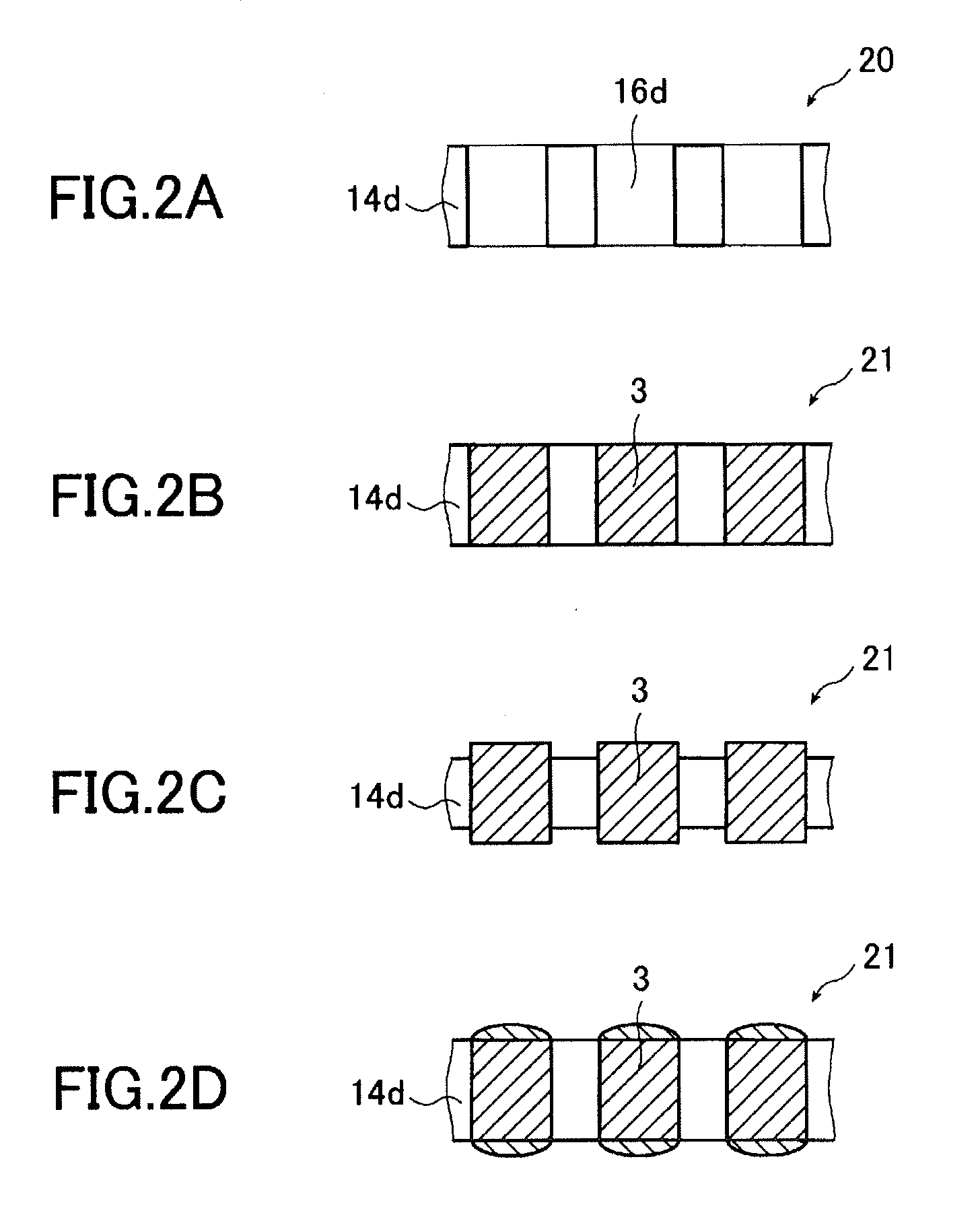
[0263]The respective treatments (A) to (G) were carried out as in Example 1 and a treatment for covering the copper protruded from the surfaces of the insulating base (anodized film) with gold was further carried out.

[0264]More specifically, the anisotropic conductive member obtained after trimming treatment in Example 1 was plated by immersion at 70° C. for 10 seconds in a gold electroless plating solution (Melplate AU-601 from Meltex Inc.).

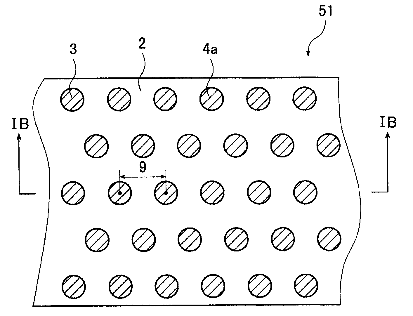
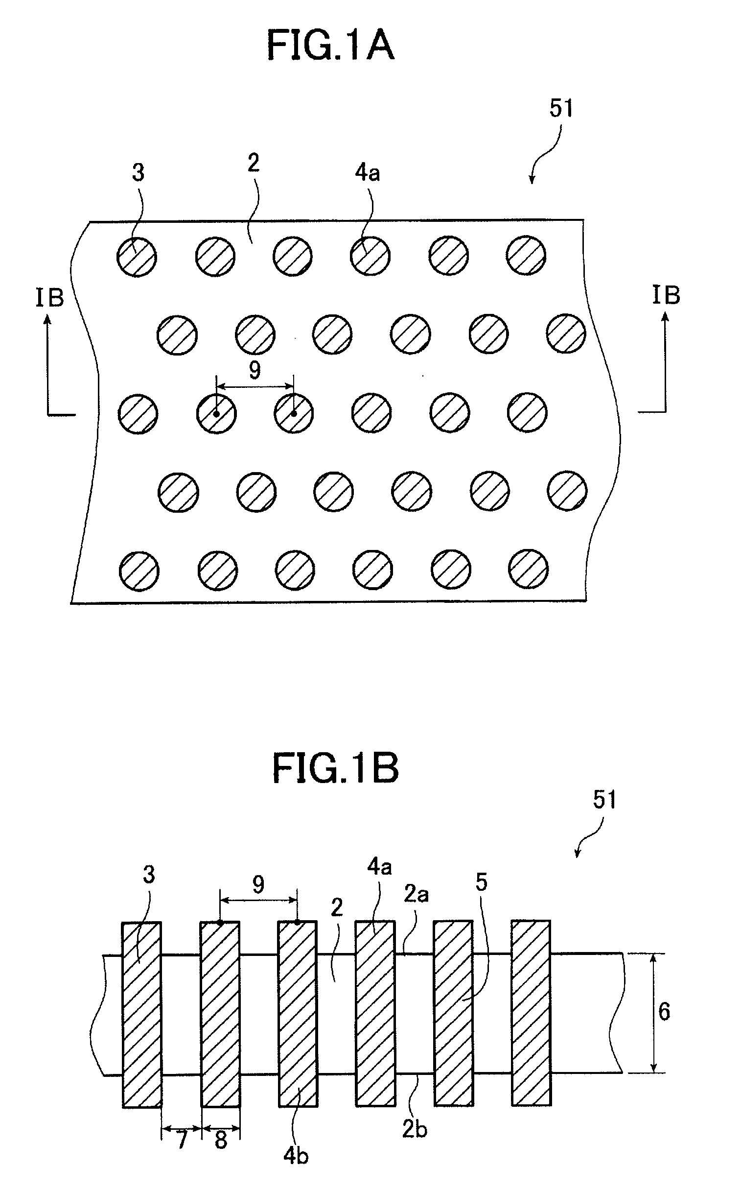
[0265]The microstructure was observed by EF-SEM as in Example 1 and the protruded portions were found to be rounded and to have a bump height increased to about 20 nm. Observation by FE-SEM confirmed that the conductive path diameter which is the size of the electrode portion was 30 nm, the member had a thickness of 100 μm, the conductive paths did not have a branched structure, and the ratio of the number of micropores A per unit area on one surface of the oxide film to the number of micropores B per unit area on the other surface of the oxide ...

example 17

[0267]Example 1 was repeated under the same conditions except that anodizing treatment in the anodizing treatment step (B) was carried out by using an electrolytic solution of 0.20 mol / L oxalic acid under the following conditions: voltage, 50V; solution temperature, 20° C.; solution flow velocity, 3.0 m / min, and trimming treatment (G) was carried out for 10 minutes, thereby manufacturing a structure (anisotropic conductive member).

[0268]The microstructure was observed by EF-SEM as in Example 1 and it was confirmed that the bump height was 40 nm, the conductive path diameter which is the size of the electrode portion was 130 nm and the member had a thickness of 90 μm.

[0269]Then, treatment (H) of Example 1 was carried out to prepare an anisotropic conductive joint package of Example 17.

example 18

[0270]Example 17 was repeated under the same conditions to prepare a structure (anisotropic conductive film).

[0271]Cu penetrating electrodes having a size of 28 μm square and a pitch of 50 μm were formed in 50 μm-thick silicon wafers and four layers were formed via the structures (anisotropic conductive films).[0272]The thermocompression bonding conditions were as follows:[0273]pressure per unit electrode area: 100 MPa; temperature: 240° C.; time: 3 minutes; and degree of vacuum: 10−1 Pa. The electric resistance in the resulting anisotropic conductive joint package was 8Ω per penetrating electrode.[0274]Then, an underfill ThreeBond 2274B available from ThreeBond Co., Ltd. was poured and penetrated into the layer containing the anisotropic conductive film from the lateral side.[0275]The underfill was cured under the thermal curing conditions of 85° C. and 45 minutes.


PUM

PropertyMeasurementUnit
diameteraaaaaaaaaa
thicknessaaaaaaaaaa
pressureaaaaaaaaaa

Abstract

An anisotropic conductive joint package in which an anisotropic conductive film is joined to at least one conductive material selected from among the group consisting of gold (Au), silver (Ag), copper (Cu), aluminum (Al), magnesium (Mg), nickel (Ni), a tin oxide doped with indium (ITO), molybdenum (Mo), iron (Fe), palladium (Pd), beryllium (Be), and rhenium (Re). The package is characterized in that: the anisotropic conductive film has an insulating base and conductive paths composed of conductive members, insulated from one another, and extending through the insulating base in the direction of the thickness of the insulating base, one ends of the conductive paths are exposed from one side of the insulating base, the other ends are exposed from the other side, the density of the conductive paths is 3,000,000 pieces / mm2 or more, the insulating base is a structural body composed of an anodic oxide film of an aluminum substrate having micropores, and each micropore does not have a branch structure along the depth. The package can be used as an anisotropic conductive member of an electronic component of a semiconductor device or the like or a connector for inspection even if the structure has a much higher degree of integration realized by drastically improving the installation density of the conductive paths.

Description

TECHNICAL FIELD[0001]The present invention relates to an anisotropic conductive film using a metal-filled microstructure and a method of manufacturing the same. More specifically, the present invention relates to an anisotropic conductive joint package which has an anisotropic conductive film using a metal-filled microstructure and a method of manufacturing the same.BACKGROUND ART[0002]An anisotropic conductive member, when inserted between an electronic component such as a semiconductor device and a circuit board, then subjected to merely the application of pressure, is able to provide an electrical connection between the electronic component and the circuit board. Accordingly, such members are highly attractive members that are widely used, for example, as connecting members for semiconductor devices and other electronic components and as inspection connectors when carrying out functional inspections, and that can be expected to be applied to optical transmission materials.[0003]I...

Claims


Application Information

Patent Timeline
Patent Type & Authority Applications(United States)
IPC IPC(8): H05K1/09H01R43/00
CPCH01L23/49827H01L23/5389H01R12/714H01L2924/0002Y10T428/24091Y10T428/24917Y10T29/49126Y10T428/24174Y10T428/24083Y10T428/24074Y10T29/4921H01L2924/00Y10T428/249953Y10T428/249956
Inventor HATANAKA, YUSUKEHOTTA, YOSHINORITOMITA, TADABUMI
Owner FUJIFILM CORP
Why Eureka
Try Eureka