Process of Making Ceria-Based Electrolyte Coating

a technology of electrolyte coating and electrolyte, which is applied in the direction of lanthanide oxide/hydroxide, final product manufacturing, sustainable manufacturing/processing, etc., can solve the problems of high material cost and high overall fabrication cost, and cannot be supported by metallic components or otherwise integrated, so as to reduce gas leakage

Inactive Publication Date: 2011-01-06
NAT RES COUNCIL OF CANADA
View PDF19 Cites 15 Cited by
  • Summary
  • Abstract
  • Description
  • Claims
  • Application Information

AI Technical Summary

Benefits of technology

[0025]By this method a coating can advantageously be produced having no open porosity and a closed porosity below 1%, and preferably below 0.5%, to reduce gas leakage across the layer. Furthermore the coating may have virtually no cracks. Gas tightness may be important in some applications. For example coatings may have a gas leakage rate measured with Helium gas at 1 psi differential pressure across the coating below 0.15 L / min / cm2, and preferably below 0.1 L / min / cm2.

Problems solved by technology

For widespread commercialization and application of these devices there are still significant challenges to overcome, primarily involving the high cost of material and high overall fabrication costs.
Traditional doped zirconia (YSZ) based electrolyte SOFCs operate at elevated temperatures of 900-1000° C. and thus cannot be supported by, or otherwise incorporate, metallic components.
Operation at these temperatures poses high demands on the thermal compatibility of the component materials and can accelerate the degradation of the cell.
Some known processes are extremely expensive, cannot be performed in air (i.e. require an inert atmosphere or vacuum) and / or cannot be scaled to commercially applicable industrial processes.
Sintering of the layer precludes continuous production and does not allow for metal parts to be included in the processing.
Some known processes do not realize satisfactory performance of reduced temperature SOFCs.
They may not provide gas barriers and they may have cracks, especially when applied to a metal substrate.
Cerium-based powder coatings made by these methods typically show microstructural defects, such as porosity and inter-lamellar gaps within the size range of the starting powder.
These coatings are also generally too thick and too coarse to be suitable for reduced-temperature SOFC electrolyte applications.
The use of acetylene fuel, in the quantities required to operate an HVOF system, can pose a significant safety risk and is consequently severely restricted in many parts of the world, including North America.
In spite of choosing acetylene as the fuel gas, as it provides the highest flame temperature, the flame enthalpy was not sufficient to fully melt suspended zirconia particles, and the zirconia coatings are not satisfactory.
Acetylene is a high temperature fuel, burning at about 3,300° C., that cannot be widely deployed commercially because of safety concerns
Ceria and zirconia-based powders are high melting point ceramics, but ceria-based powders have deposition issues that zirconia-based powders do not.

Method used


Image

  • Process of Making Ceria-Based Electrolyte Coating
  • Process of Making Ceria-Based Electrolyte Coating
  • Process of Making Ceria-Based Electrolyte Coating

Examples


example 1

HVOF Sprayed Electrolyte

Apparatus

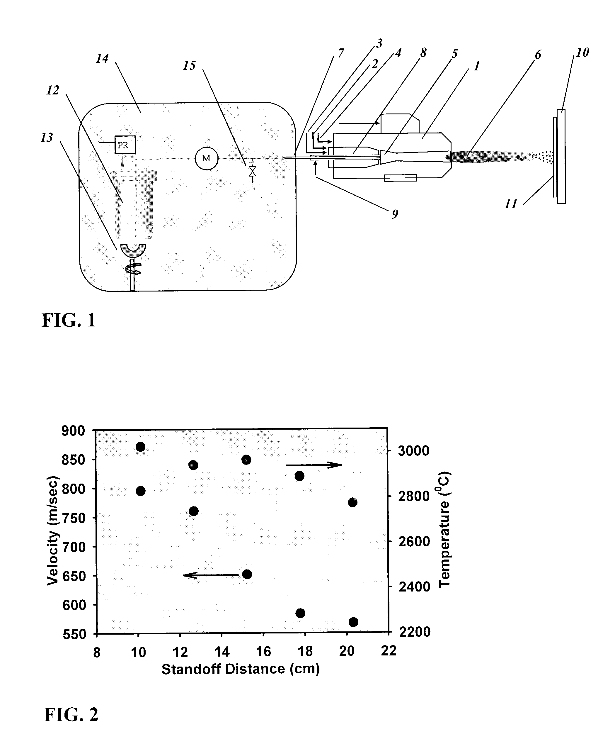
[0078]A thermal spray apparatus, as shown in FIG. 1 was assembled. A commercially available HVOF gun used (model number DJ-2700, Sulzer-Metco, Westbury, N.Y., USA) is capable of generating supersonic flame velocities and sufficiently high temperatures.

[0079]The DJ-2700 gun has a stainless steel tube inserted into the 1.5 mm inner diameter feedstock supply tube throughout its length so that the stainless steel tube had an opening flush with the opening of the feedstock supply tube at the combustion chamber. The stainless steel tube was a 19 gauge tube having an outer diameter just over 1 mm, and an inner diameter of about 0.8 mm, although other arrangements that do not provide excessive resistance to both the coolant and the feedstock suspension flows would be expected to work equally well. This is how the inert gas and feedstock suspension were supplied to the DJ-2700 gun.

[0080]The suspension of 2.5 wt. % solids in a 3:1 mixture of ethylene glycol to...

example 2

Plasma Sprayed Electrolyte

Apparatus

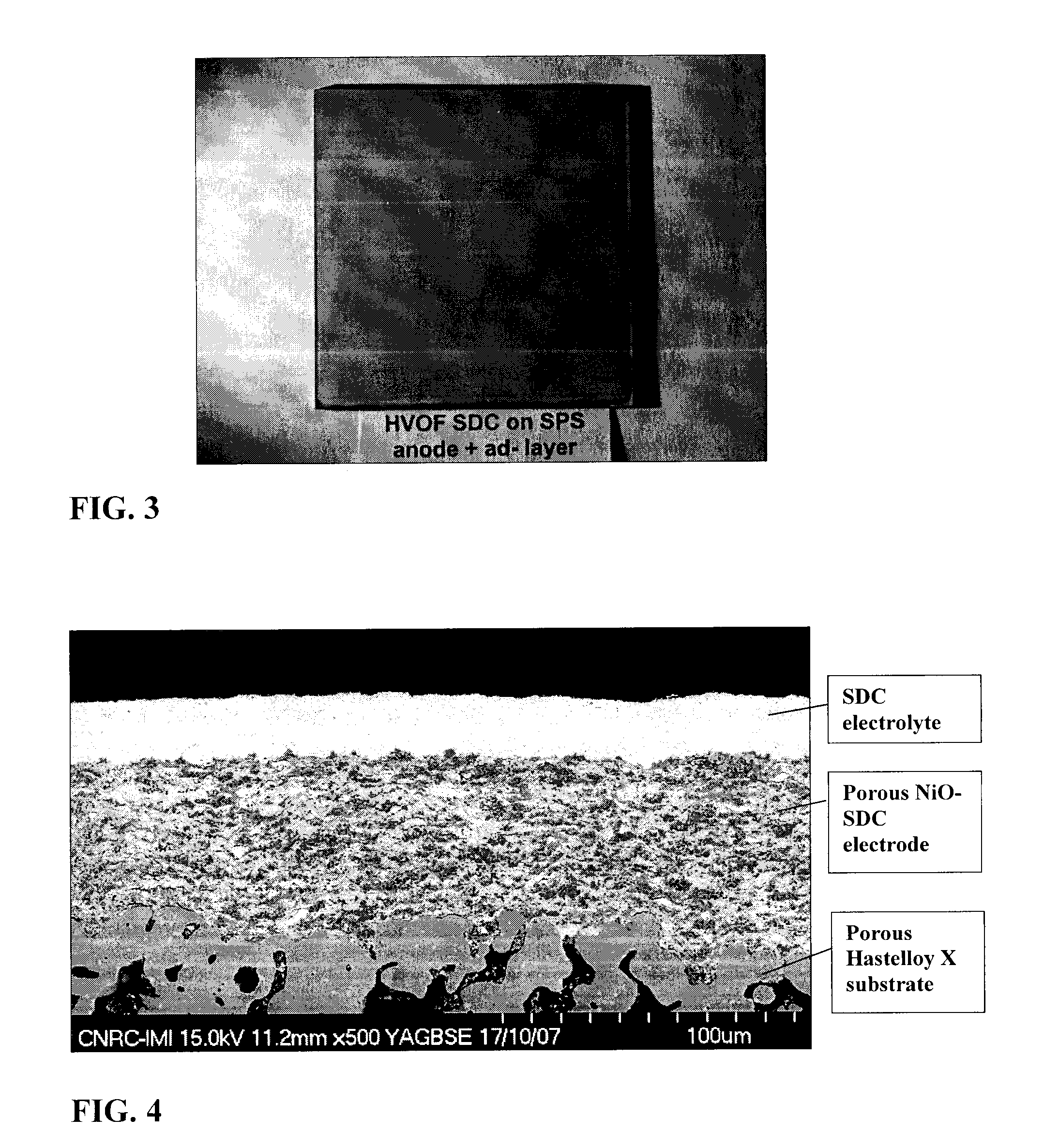
[0104]In this example, a SDC electrolyte of approximately 27 μm thickness was fabricated by suspension plasma spraying using an axial injection plasma torch (Axial III, Northwest Mettech Corp., North Vancouver, BC, CAN). The SDC electrolyte was deposited onto a porous, 25 micron thick suspension plasma sprayed anode, composed of 70 wt. % nickel-oxide and 30 wt. % SDC. The anode, in turn, was supported by a metallic Hastelloy X substrate with a porosity of 27.5% and a mean pore size of about 10 μm. As such the electrolyte is applied to a comparable surface as that of the electrolyte of example 1.

[0105]This example was first published in Dynamic Evaluation Of Low-Temperature Metal-Supported Solid Oxide Fuel Cell Oriented Towards Auxiliary Power Units (Z. Wang et al., Journal of Power Sources, Vol. 176, Issue 1, January 2008, 90-95).

[0106]For the electrolyte, the suspension of 5 wt % solids in ethanol was prepared from micron to sub-micron sized SDC p...

example 3

Suboptimal Fuel to Oxygen Ratio

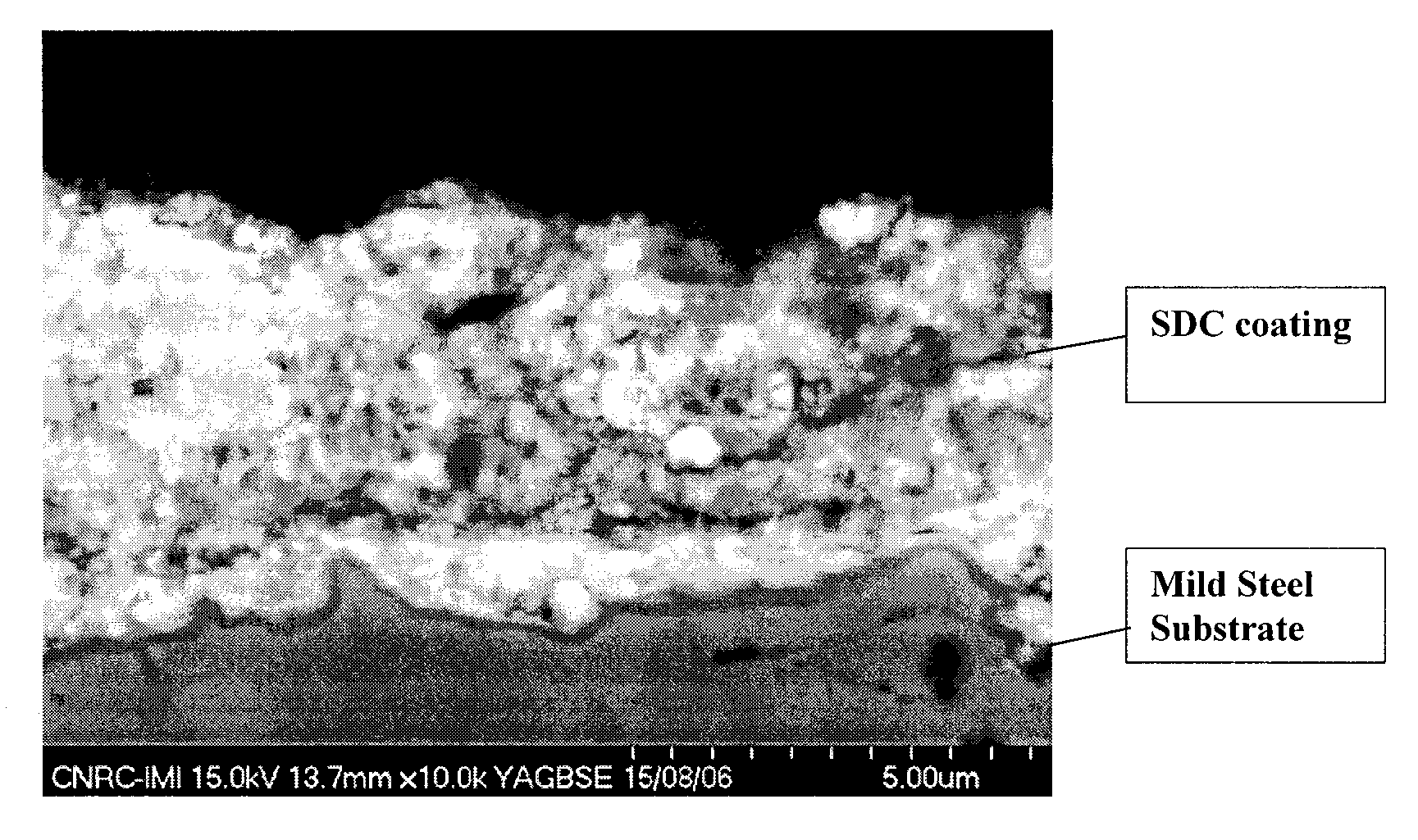
[0121]A SDC coating of approximately 15 μm thickness was deposited on a stainless steel 430 substrate. For the coating, the suspension of 5 wt. % solids in ethanol was prepared from nanosized SDC (˜20 nm particle size). The suspension was injected into the DJ 2700 spray gun at a flow rate of 50 mL / min. During deposition, the substrate temperature was maintained at 420° C. using backside air and water cooling, as well as forced-air cooling at the front side. Experimental conditions were the following:

i.Propylene flow 80 slpmii.Oxygen flow279 slpmiii.Air flow (shroud)202 slpmiv.Nitrogen flow 15 slpm

Spray Jet Particle Ranking

[0122]Prior to spraying the coating, on-line measurements of the particle states were performed. These measurements indicated that the highest mean particle temperature of 2670° C.±100° C. is reached 15 cm after the gun exit nozzle at an average particle velocity of 660 m / sec. FIG. 14 shows a graph of the axial profile of average part...


PUM

PropertyMeasurementUnit
mean particle diameteraaaaaaaaaa
temperatureaaaaaaaaaa
velocityaaaaaaaaaa

Abstract

It has been surprisingly found that injecting ceria-based particles (mean size less than 200 nm) suspended in a combustible organic solvent into a plume having a maximum temperature between about 2,600° C. and 4,000° C. to impart a mean temperature to the particles from about 2,600° C. to about 3,800° C., and to accelerate the particles to a mean velocity between about 600 to 1000 m/s, produces a thin, uniform, dense, crack-free, nanocrystalline ceria-based coating, which may be applied on porous cermet or metal substrate, for example. The physical environment of a high-velocity oxy-fuel (HVOF) thermal spraying gun suitably ably deployed using standard fuels produces these conditions. The method of the present invention is particularly useful for the cost-effective fabrication of ceria-containing electrolytes for solid oxide fuel cells (SOFCs).

Description

CROSS-REFERENCE TO RELATED APPLICATIONS[0001]The present application claims the benefit of U.S. provisional application Ser. No. 61 / 064,272 to Jorg Oberste Berghaus et al., filed Feb. 25, 2008, entitled “Process for Making Ceria-Based Electrolyte Coating”.FIELD OF THE INVENTION[0002]The present invention relates in general to a process of producing ceria-based electrolyte coatings applicable in reduced temperature solid oxide fuel cells. In particular, the invention produces thermal sprayed ceria-based coatings that can be deposited onto a metal substrate in air to produce a thin, low-porosity layer without sintering.BACKGROUND OF THE INVENTION[0003]Solid oxide fuel cells (SOFCs) are highly efficient devices that convert hydrogen and hydrocarbon fuels electrochemically into electricity and heat with low environmental pollution and greenhouse gas emission. Most SOFCs comprise an anode or fuel electrode, a cathode or air electrode, and an electrolyte separating the electrodes. At the ...

Claims


Application Information

Patent Timeline
Patent Type & Authority Applications(United States)
IPC IPC(8): C23C4/10B05D5/12C01F17/235C01F17/241
CPCC01F17/0043C23C4/105C23C4/121Y02E60/525H01M8/126H01M2008/1293Y02E60/521H01M8/1213C23C4/11C23C4/123Y02E60/50Y02P70/50C01F17/241C01F17/235
Inventor BERGHAUS, JORG OBERSTELEGOUX, JEAN-GABRIELMOREAU, CHRISTIAN
Owner NAT RES COUNCIL OF CANADA
Why Eureka
Try Eureka