
Fine carbon fiber, fine short carbon fiber, and manufacturing method for said fibers

a technology of carbon fiber and manufacturing method, which is applied in the direction of catalyst activation/preparation, metal/metal-oxide/metal-hydroxide catalyst, physical/chemical process catalyst, etc., can solve the problem of not achieving sufficient conductivity, difficult to cleave strong carbon sp-2 bond, and insufficient conductivity. , to achieve the effect of small energy consumption, good conductivity and large bonding strength

Inactive Publication Date: 2011-01-06
UBE IND LTD
View PDF5 Cites 19 Cited by
  • Summary
  • Abstract
  • Description
  • Claims
  • Application Information

AI Technical Summary

Benefits of technology

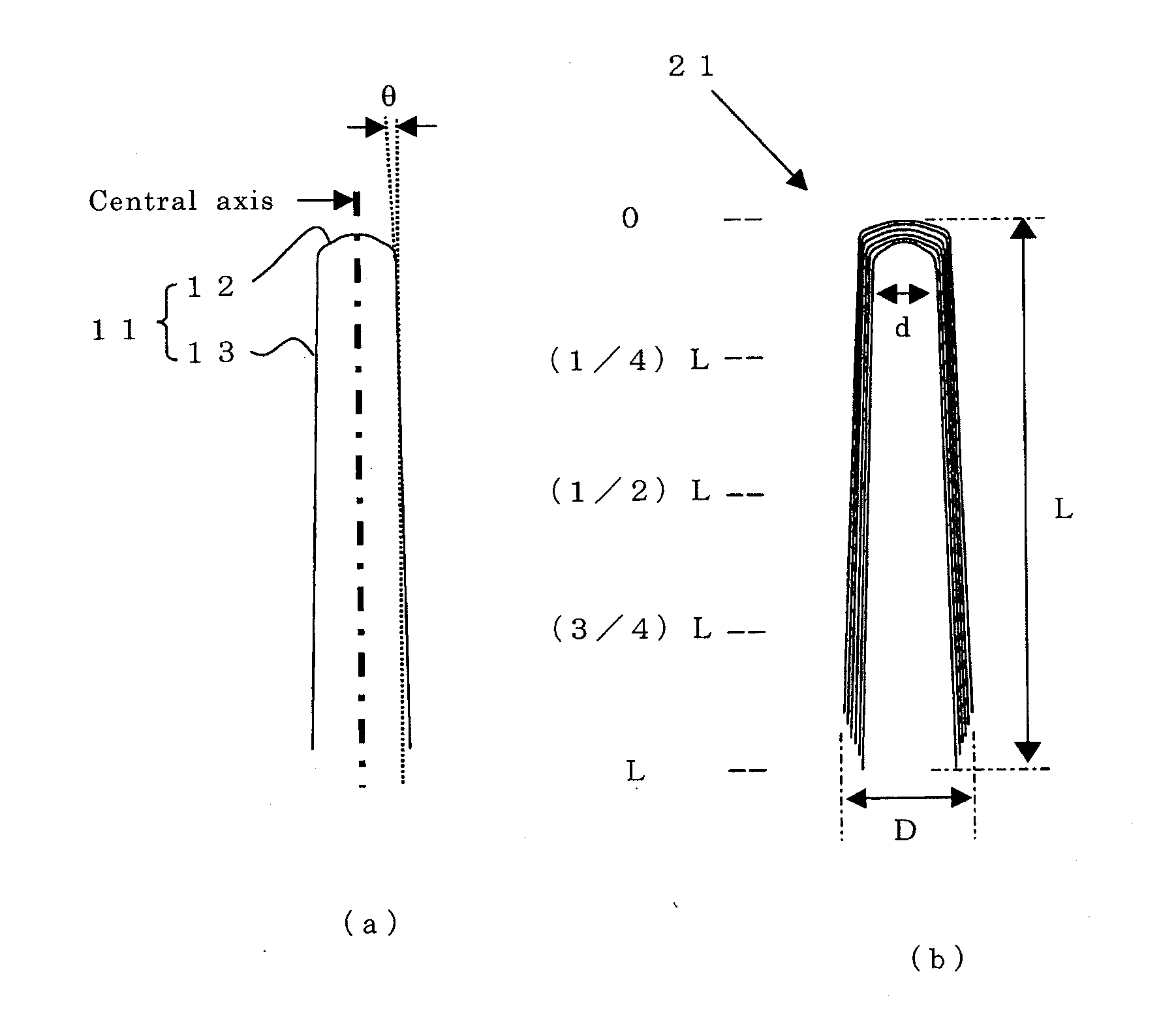
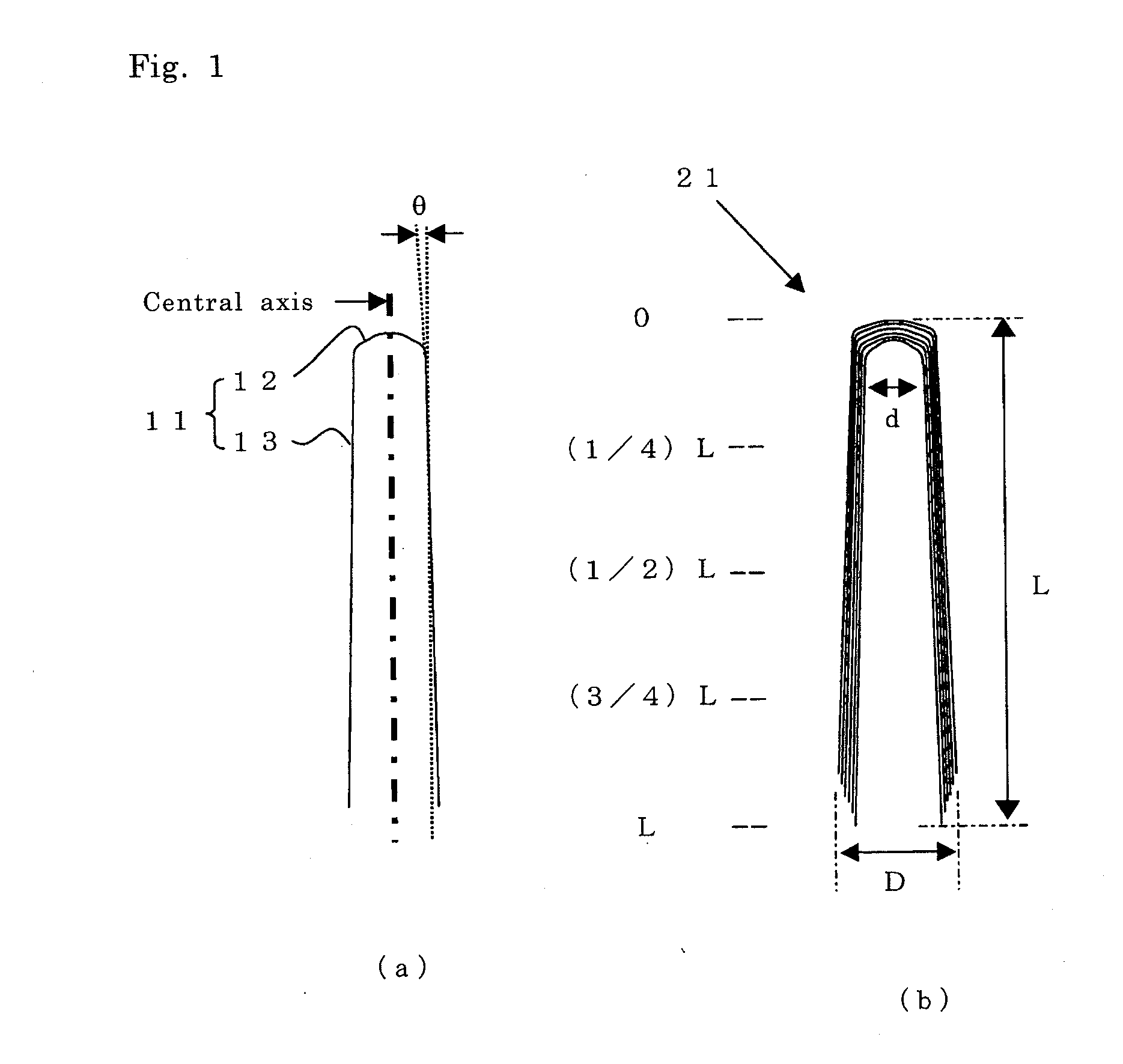
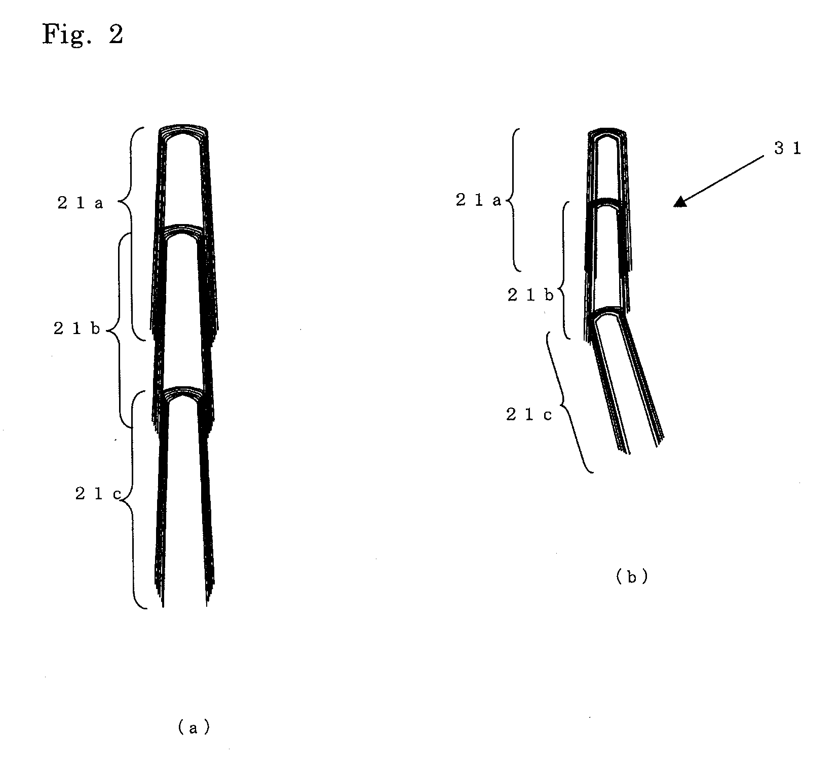
[0056]A fine carbon fiber of the present invention has a fiber structure in which an open end of a graphite-net plane constituting the fiber is exposed in the side peripheral surface of the fiber with an appropriate distance and the side peripheral surface consisting of the graphite-net plane forms a small angle with the fiber axis. The bond of this fine carbon fiber in the direction of the fiber axis in the temple-bell-shaped structural unit aggregate is a continuous carbon SP2 bond, whose bonding strength is large and good conductivity can be achieved in the fiber axis direction. Furthermore, the fiber has regions where open ends of the graphite-net planes are exposed in the side peripheral surface of the fiber with an appropriate distance at a frequency in terms of aspect ratio of about 2 to 150 along the fiber axis direction of this carbon fiber. Thus, conductivity in a long-axis direction in a single fiber and conductivity between adjacent fibers can be well balanced.
[0057]Furthermore, in the region around open-end of the temple-bell-shaped structural unit aggregate, a bonding part is formed with carbon fundamental planes that are oblique to the fiber axis. In other words, this bonding part is a part where temple-bell-shaped structural unit aggregates are bonded each other mainly by the bonding between the carbon fundamental planes, that is, weak bonding force of van der Waals force. Therefore, when shear stress is applied to this part, it can easily cause sliding between the carbon fundamental planes, so that the temple-bell-shaped structural unit aggregate slides off or is pulled out of the bonding part, resulting in cutting of the fiber.
[0058]A method for shortening the fine carbon fiber into the fine short carbon fiber is, as a procedure, the same as the ball mill cutting method described in (3) as a conventional fiber-shortening method. However, in a conventional fine carbon fiber, the substantially whole fiber is connected by carbon SP2 bond, and therefore, cleaving this bond requires enormous amount of energy and the outer wall of the fiber after cutting is considerably damaged. In contrast, a fine carbon fiber of the present invention has a structure where temple-bell-shaped structural unit aggregates are bonded via van der Waals force, and therefore, the bonding part can be cleaved with a relatively smaller energy and furthermore, the fiber can be shortened by a small energy, so that the fine short carbon fiber obtained can be undamaged. Furthermore, fiber shortening with a small energy means small impact on a ball mill vessel and balls and thus, it is also a distinctive feature that contamination due to scraping of such vessel or balls is reduced. This is confirmed by the facts that, in the fibers described in Table 2 (Reference Example B1 and Example B1-6), a carbon layer gap as determined by XRD is little changed before and after fiber shortening, that true specific gravity is substantially unchanged, and that a surface area does not increase corresponding to fiber shortening.
[0059]Furthermore, according to the process for manufacturing a fine carbon fiber, a fine carbon fiber less contaminated with impurities can be efficiently produced, so that a fine short carbon fiber prepared by applying shear stress to the above fiber is also highly pure and fiber shortening, that is, separation between bonding sites, does not require much energy, resulting in less contamination by impurities from a ball mill and the like. Furthermore, the use of a fine short carbon fiber of the present invention reduces energy required for homogeneously mixing the fiber with a resin or a powder. For example, since mixing with a resin does not require a large shear force at a high temperature, manufacturing of a conductive composite which keeps characteristic resin properties can be obtained. In mixing with solid materials, a conductive composition keeping characteristic solid properties can be manufactured without damaging the crystallinity of the solid materials.

Problems solved by technology

Among these, vapor growth using catalyst particles attracts attention as an inexpensive synthetic method, but is not established in a large scale.
There is, therefore, a problem that in a composite with a polymer using carbon nanotube as a conductive filler, if contact between fibers is inadequate, sufficient conductivity is not obtained.
Furthermore, since a cylindrical graphite-net plane in carbon nanotube having this structure consists of a SP2-bond carbon cylinder, it is difficult to cleave strong carbon SP-2 bond by an industrial method generally used (ball mill, bead mill, or the like) for further shortening the fiber to give an industrially available fine short carbon fiber without generating structural defects in the fiber surface.
However, since conductivity in the fiber axis direction is extremely low as described above, not only a fish bone type carbon fiber but also a further shortened fiber are unsuitable as a conductive material.
However, this fiber contains a nitrogen atom chemically bonded to a carbon atom in a graphite-net plane, so that structural distortion is introduced in the graphite-net plane, leading the problem of poor crystallinity, that is, lower conductivity.
Although chemical composition analysis for the fiber structure is not described at all in this reference, nitrogen which are not inert are contained in a raw material in a very high concentration (59 wt %), so that the fiber structure would also contain a nitrogen atom chemically bonded to a carbon atom, leading to structural disturbance.
Furthermore, since a ratio of a product weight to a catalyst weight is as significantly low as about 6, the growth of fiber is insufficient, leading to a lower aspect ratio.
Thus, in terms of conductivity in a long-axis direction of a single fiber, there is a problem as described above for the fish bone carbon fiber.
Furthermore, since an aspect ratio is lower due to insufficient fiber growth, it is difficult to give conductivity or reinforcement to a composite with a polymer.
Furthermore, since a ratio of a product weight to a catalyst weight is as low as 21, the process is inefficient as a manufacturing process and impurities are contained in a large amount, leading to limited number of applications.
In this method, fibers are cut one by one, and therefore, the method is not suitable for large-scale production.
This method has a problem that a carbon wall is significantly damaged.
This method also has a problem of yield reduction due to oxidation.
In this method, the side surface of a fiber is considerably damaged and at the same time, the fiber is contaminated by impurities from a ball mill.
This method also has a problem in an yield because a fluorinated moiety is eliminated, and an apparatus becomes larger.
This method is convenient, but is not suitable for large-scale production.

Method used


Image

  • Fine carbon fiber, fine short carbon fiber, and manufacturing method for said fibers
  • Fine carbon fiber, fine short carbon fiber, and manufacturing method for said fibers
  • Fine carbon fiber, fine short carbon fiber, and manufacturing method for said fibers

Examples


examples

[0119]There will be described Examples of the present invention together with Comparative Examples.

example a1

[0120]In 500 mL of ion-exchanged water were dissolved 115 g of cobalt nitrate [Co(NO3)2.6H2O: molecular weight 291.03] (0.40 mol) and 102 g of magnesium nitrate [Mg(NO3)2.6H2O: molecular weight 256.41] (0.40 mol), to prepare raw-material solution (1). Furthermore, 220 g of powdery ammonium bicarbonate [(NH4)HCO3: molecular weight 79.06] (2.78 mol) was dissolved in 1100 mL of ion-exchanged water, to prepare raw-material solution (2). Next, raw-material solutions (1) and (2) were mixed at a reaction temperature of 40° C., after which the mixture was stirred for 4 hours. The precipitate formed was filtered, washed and then dried.

[0121]The product was calcined and pulverized with a mortar to provide 43 g of a catalyst. A crystal lattice constant “a” (cubic system) of the spinel structure in this catalyst was 0.8162 nm, and a metallic element ratio in the spinel structure of the substitutional solid solution was Mg:Co=1.4:1.6.

[0122]A quartz reaction tube (inner diameter: 75 mmφ, height: ...

example a2

[0125]In 900 mL of ion-exchanged water was dissolved 123 g of cobalt nitrate [Co(NO3)2.6H2O: molecular weight 291.03] (0.42 mol) and then was added 17 g of magnesium oxide [MgO: molecular weight 40.30] (0.42 mol), and the mixture was mixed to prepare raw-material slurry (1). Furthermore, 123 g of powdery ammonium bicarbonate [(NH4)HCO3: molecular weight 79.06] (1.56 mol) was dissolved in 800 mL of ion-exchanged water, to prepare raw-material solution (2). Next, raw-material slurry (1) and raw-material solution (2) were mixed at room temperature, after which the mixture was stirred for 2 hours. The precipitate formed was filtered, washed and then dried. The product was calcined and pulverized with a mortar to provide 48 g of a catalyst. A crystal lattice constant “a” (cubic system) of a spinel structure in this catalyst was 0.8150 nm, and a metallic element ratio in the spinel structure of the substitutional solid solution was Mg:Co=1.2:1.8.

[0126]A quartz reaction tube (inner diamete...


PUM

PropertyMeasurementUnit
Temperatureaaaaaaaaaa
Lattice constantaaaaaaaaaa
Percent by massaaaaaaaaaa

Abstract

A novel fine carbon fiber is produced by vapor growth, in which a graphite-net plane consisting of carbon atoms alone forms a temple-bell-shaped structural unit comprising closed head-top part and body-part with open lower-end, where an angle θ formed by a generatrix of the body-part and a fiber axis is less than 15°, 2 to 30 of the temple-bell-shaped structural units are stacked sharing a central axis to form an aggregate, and the aggregates are connected in head-to-tail style with a distance, thereby forming a fiber. Furthermore, a fine short carbon fibers with excellent dispersibility can be obtained by shortening the fine carbon fiber.

Description

TECHNICAL FIELD[0001]The present invention relates to a fine carbon fiber and a fine short carbon fiber, which are highly conductive, as well as a process for efficiently manufacturing such a carbon fiber and a short carbon fiber. In particular, the invention relates to a process for manufacturing a fine carbon fiber by vapor growth using a catalyst, as well as a process for manufacturing a fine short carbon fiber prepared by applying shear stress to the above fine carbon fiber for further shortening.BACKGROUND ART[0002]Fine carbon fibers represented by, for example, a cylindrical tube type, a fish bone type (cup stack type) and a card-shaped (platelet) type are expected to be used in various applications because of their shape and morphology. In particular, a cylindrical tube type fine carbon fiber (carbon nanotube) has attracted the attention as a next-generation conducting material because it is excellent in properties such as strength and electric conductivity in comparison with...

Claims


Application Information

Patent Timeline
IPC IPC(8): D01F9/12
CPCB01J23/005B01J23/78B01J37/03B82Y30/00B82Y40/00C01B31/0233Y10T428/2918C01B2202/34C01B2202/36D01F9/1278D10B2101/122Y10T428/2982C01B31/0293C01B32/162C01B32/18
Inventor NISHIO, MASAYUKIMATSUURA, TSUNAOFUKUDA, KENJI
Owner UBE IND LTD
Learn More