
Method of manufacturing the microporous polyolefin composite film with a thermally stable layer at high temperature

a polyolefin composite film and thermal stability technology, applied in the direction of cell components, cell component details, transportation and packaging, etc., can solve the problems of battery overheating or igniting, electric short between the electrodes, and battery generation heat, etc., to achieve excellent thermal stability, excellent permeability, and excellent stability of the coating layer

Inactive Publication Date: 2011-02-10
SK INNOVATION CO LTD
View PDF10 Cites 29 Cited by
  • Summary
  • Abstract
  • Description
  • Claims
  • Application Information

AI Technical Summary

Benefits of technology

[0013]An object of the present invention is to provide a method of manufacturing a microporous polyolefin composite film which has excellent permeability and also excellent thermal stability in high temperature, more particularly, to provide a method of manufacturing a microporous polyolefin composite film with a thermally stable layer at high temperature which has excellent stability in high temperature organic electrolytes, high meltdown temperature and lower shrinkage at high temperature.Technical Solution

Problems solved by technology

In case of the lithium secondary battery, if the thermal stability of the separator is deteriorated, the separator may be damaged or deformed by increase of temperature in the battery and thus an electrical short may occur between the electrodes.
Therefore, there is a risk that the battery may be overheated or ignited.
If the electrical short occurs between the electrodes due to dendrite generated during charging and discharging processes of the battery, the battery generates heat.
However, in case of the electron beam crosslinking, there are some disadvantages such as necessity for an electron beam crosslinking apparatus, a limitation of production speed, a variation in quality according to non-uniform crosslinking.
And in case of the chemical crosslinking, there are also some disadvantages in that it has complicated extruding and mixing processes, and a gel may be generated at a film due to the non-uniform crosslinking.
However, in this method, there are some disadvantages such as increase of extruding load, deterioration of the extruding and mixing ability, and occurrence of incomplete stretching due to using of the ultra high molecular weight polyethylene, as well as inferiority in the mixing, variation in quality and generation of pinholes due to using of the inorganic particles.
Further, physical properties of the film are also deteriorated due to lack of interface compatibility between the inorganic matter and the high molecular resin.
Further, since an additional is also needed to separate and remove the used the inorganic particles, the manufacturing process is very complicated.
However, there is a disadvantage that the microporous film manufactured by this method has a non-uniform thickness due to particulate heat-resistant resin.
If the microporous film has the non-uniform thickness, the defective proportion in assembling of battery is increased and thus the productivity is reduced.
Also, after the assembling of battery, an electrical short occurs, thereby deteriorating safety.
In these methods, a polypropylene layer is provided by a dry or wet process, but a heat-resistant layer is stretched and it is difficult to basically prevent heat shrinkage due to limitation of a melting point of polypropylene.
Therefore, there is limitation in manufacturing of a high heat-resistant separator.
However, since the resin is easily dissolved or gelled in an organic solvent such as propylene carbonate, ethylene carbonate, diethyl carbonate, dimethyl carbonate, and ethyl methyl carbonate, which is used as a non-aqueous electrolyte of a battery, there is limitation in enhancing the thermal stability of the battery.
However, it is difficult to provide efficient permeability by a pore forming method in which a single resin is phase-separated by a dry process when forming a coating layer of the film.
Further, since phase separation size and uniformity are considerably changed according to the drying conditions such as humidity, temperature and so on, there is limitation in manufacturing the separator having uniform quality.
With respect to the heat-resistance as one of the main characteristics of the battery separator, the conventional methods have a limitation in the heat-resistance of the resin itself, or the applying of the heat-resistant resin does not contribute to the improvement of the heat-resistance of the separator.
And other physical properties like gas permeability are low or do not mentioned, and also the quality uniformity is poor.
Further, when the separator manufacture by the conventional methods are actually applied to the battery, there is a problem that it is not provide constant thermal stability under the conditions such as high temperature, high voltage and organic electrolytes.

Method used


Image

  • Method of manufacturing the microporous polyolefin composite film with a thermally stable layer at high temperature
  • Method of manufacturing the microporous polyolefin composite film with a thermally stable layer at high temperature
  • Method of manufacturing the microporous polyolefin composite film with a thermally stable layer at high temperature

Examples


example 1

[0094]In order to prepare the polyolefin microporous film, high density polyethylene having a weight average molecular weight of 3.8×10⁵ is used, and a mixture in which dibutyl phthalate and paraffin oil (kinematic viscosity at 40° C.: 160 cSt) is mixed at a rate of 1:2 is used as a diluent, and each content of the polyethylene and the diluent is 30 wt % and 70 wt %, respectively.

[0095]This composition is extruded at a temperature of 240° C. using a dual-axial compounder having a T-die, and passed through an area, of which temperature is set to 180° C., so as to induce a phase separation, and then a sheet is prepared using a casting roll. The sheet is prepared by a successive bi-axial stretching method in which a stretching rate is six times in each of a MD and a TD, and a stretching temperature is 121° C. Herein, a heat-setting temperature is 128° C., and a heat-setting width is 1-1.2-1.1. A final film has a thickness of 16 μm and a gas permeability of 3.5×10⁻⁵ Darcy.

[0096]A soluti...

example 2

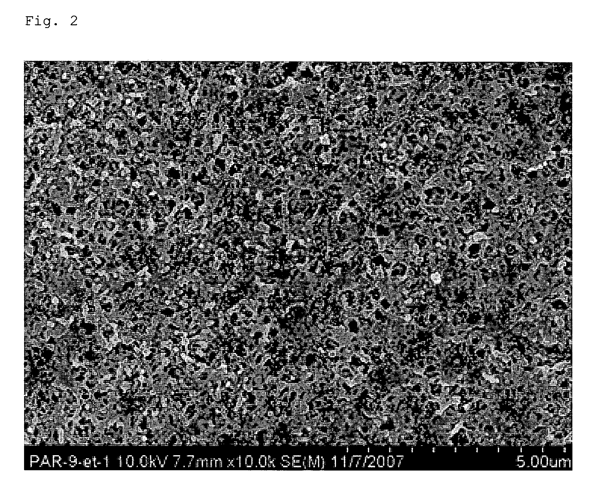
[0098]The same the polyolefin microporous film as in the example 1 is used, and the solution for forming the coating layer is prepared by dissolving polyarylate (PAR) having a glass transition temperature of 201° C. in NMP solvent. In the composition of the solution, resin / solvent is 11 / 89 wt %. One surface is coated by the bar coating method, and the coated film is dried in an oven of 50° C. for 2 minutes, and impregnated with ethanol nonsolvent and then dried again in an oven of 60° C. for 30 minutes.

[0099]A photograph of a scanning electron microscope showing a surface of the manufactured microporous polyolefin composite film is illustrated in FIG. 2.

example 3

[0100]The same the polyolefin microporous film as in the example 1 is used, and the solution for forming the coating layer is prepared by dissolving polyetherimide (PEI) having a glass transition temperature of 217° C. in NMP solvent. In the composition of the solution, resin / solvent is 13 / 87 wt %. One surface is coated by the bar coating method, and the coated film is dried in an oven of 50° C. for 2 minutes, and impregnated with iso-propanol nonsolvent and then dried again in an oven of 60° C. for 30 minutes.


PUM

PropertyMeasurementUnit
particle sizeaaaaaaaaaa
temperatureaaaaaaaaaa

Abstract

Provided is a method of manufacturing a microporous polyolefin composite film with a thermally stable porous layer at high temperature, particularly, to a method of manufacturing a microporous polyolefin composite film with a thermally stable porous layer at high temperature, comprising preparing a polyolefin microporous film using a composition containing a polyolefin resin; coating a solution, in which a high heat-resistant resin is dissolved in a solvent, on one surface or both surfaces of the polyolefin microporous film; phase-separating the polyolefin microporous film coated with the solution by contacting with a nonsolvent after the coating; and drying the polyolefin microporous film so as to remove the solvent and nonsolvent remained after the phase-separating, and thus forming the thermally stable layer at high temperature.

Description

TECHNICAL FIELD[0001]The present invention relates to a method of manufacturing a microporous polyolefin composite film which has excellent permeability and excellent thermal stability in high temperature electrolyte.BACKGROUND ART[0002]A polyolefin-based microporous film has been widely used as a battery separator, a separator filter, and a membrane for microfiltration, due to its chemical stability and excellent physical properties. Meanwhile, for the battery separator, the microporous structure is required to have a spatial separation function between positive and negative electrodes and a microporous structure for high ionic conductivity. Recently, it has been further required to enhance the characteristic of the separator for the thermal stability and electrical stability upon charging and discharging of the secondary battery, according to the tendency of the secondary battery toward the high-capacity and high-power. In case of the lithium secondary battery, if the thermal stab...

Claims


Application Information

Patent Timeline
Patent Type & Authority Applications(United States)
IPC IPC(8): H01M2/16B32B5/32B32B15/085B05D5/12H01M50/417H01M50/451H01M50/457H01M50/489H01M50/491H01M50/494
CPCH01M2/1653H01M2/166Y10T428/2495H01M10/052H01M2/1686Y02E60/10H01M50/446H01M50/417H01M50/489H01M50/451H01M50/457H01M50/491H01M50/494B01D69/1213B01D71/26B01D71/261B01D71/262B01D67/0088B01D71/50B01D71/481B01D67/0095B01D69/1216B01D69/141B01D69/148B01D67/00793B01D67/009H01M50/403B01D2325/22B01D2323/12B01D2325/04B01D2325/20B01D2325/24
Inventor LEE, JEANSUNG, JONGMOONKIM, YONGKYOUNGLEE, YOUNGKEUN
Owner SK INNOVATION CO LTD
Learn More