Thermal interface device

a technology of heat-generating components and interface devices, which is applied in semiconductor devices, lighting and heating apparatus, and semiconductor devices. it can solve the problems of reducing the reliability of hgc devices, limiting factors, and difficult cooling requirements for new generation heat-generating components (hgc), so as to improve the rate of waste heat removal, reduce power consumption, and be suitable for large volume production

Inactive Publication Date: 2011-07-28
VETROVEC JAN
View PDF0 Cites 18 Cited by
  • Summary
  • Abstract
  • Description
  • Claims
  • Application Information

AI Technical Summary

Benefits of technology

[0024]In yet another preferred embodiment of the present invention, the moving (rotating or traveling magnetic) magnetic field may be generated by stationary electromagnets operated by alternate current in an appropriate poly-phase relationship. In a still another embodiment of the present invention, the coolant is an arbitrary liquid flowed in a closed channel with a substantially constant radius of curvature. The coolant flow is induced by a rotating impeller (impeller drive) spun by mechanical means, rotating magnetic field, moving magnetic field, or by electromagnetic induction. In a variant of the invention the coolant may be directed to impinge onto the flow channel wall opposite to the HGC to further improve the rates for removal of waste heat from the HGC.
[0025]Accordingly, it is an object of the present invention to provide a heat transfer device (HTD) for removing waste heat from HGC. The HTD of the present invention is simple, compact, lightweight, self-contained, can be made of materials with a coefficient of thermal expansion (CTE) matched to that of the HGC, requires relatively little power to operate, and it is suitable for large volume production.

Problems solved by technology

Cooling requirements for the new generation of heat-generating components (HGC) are very challenging for thermal management technologies of prior art.
Traditional heat sinks and heat spreaders have a large thermal resistance, which may contribute to elevated junction temperatures and, may cause reduced HGC device reliability.
As a result, removal of heat often becomes the limiting factor and a barrier to further performance enhancements for HGC.
Waste heat must be effectively removed from the LED chip to reduce junction temperature, thereby prolonging LED life and making LED cost effective over traditional lighting sources.
Anodes in x-ray tubes are subjected to very high thermal loading.
Such rotating anodes inside a vacuum enclosure are impractical for use in a new generation of x-ray tubes for use in compact and portable devices in medical and security applications.
However, even with heat spreading materials having extremely high thermal conductivity such as diamond films and certain graphite or graphene fibers, a significant thermal gradient is required to conduct large amount of heat even over short distances.
In addition, passive heat spreaders are not conducive to temperature control of the HGC.
Known forced convection systems have many components, are bulky, heavy, and have geometries that require the coolant to make complex directional changes while traversing the coolant loop.
Such directional changes are a potential source of increased flow turbulence causing higher pressure drop in the loop and, therefore, necessitate higher pumping power.
In optical components such as laser crystals, coolant turbulence may result in deleterious fluid-induced vibrations causing misalignment of optical beams.
Such configurations may not self-contained and may be impractical for many applications because they may have a large size, may not sealed, may use incompatible materials, and may have large electromagnetic interference (EMI).
In addition, above disclosures do not address the challenges of handling and pumping liquid metal, namely:1) Galinstan has a specific gravity of about 6.4, which means that galinstan flow loop may require nearly 7-times more pumping power to operate than a comparable water flow loop having the same flow velocity.2) Gallium alloys have a tendency to form amalgams with other metals, which may result in severe corrosion in commonly used engineering metals.
In addition, the solid inter-metallic compounds produced by the corrosive action may form deposits inside the liquid metal flow channel, impeding the heat transfer, and possibly block the flow channels.3) Pumping of liquid metal with an electromagnetic pump may be very simple in theory, but it may be challenging in practice due to possible complex magneto-hydro-dynamic (MHD) boundary layers and MHD instabilities.4) Specific heat of liquid metal per unit volume may be only about half of that of water.
This means that, a liquid metal cooling loop operating at low velocity may not be much more effective (and may be actually less effective) than a comparable water loop.
In summary, prior art does not teach a heat transfer device capable of removing heat at very high fluxes on the order of several hundreds of watts per square centimeter that is also compact, lightweight, self-contained, capable of accurate temperature control, has a low thermal resistance, and requires very little power to operate.

Method used


Image

  • Thermal interface device
  • Thermal interface device
  • Thermal interface device

Examples


Embodiment Construction

[0063]Selected embodiments of the present invention will now be explained with reference to drawings. In the drawings, identical components are provided with identical reference symbols in one or more of the figures. It will be apparent to those skilled in the art from this disclosure that the following descriptions of the embodiments of the present invention are merely exemplary in nature and are in no way intended to limit the invention, its application, or uses.

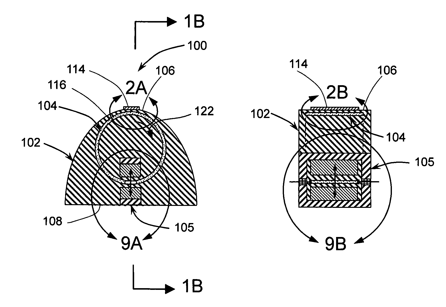
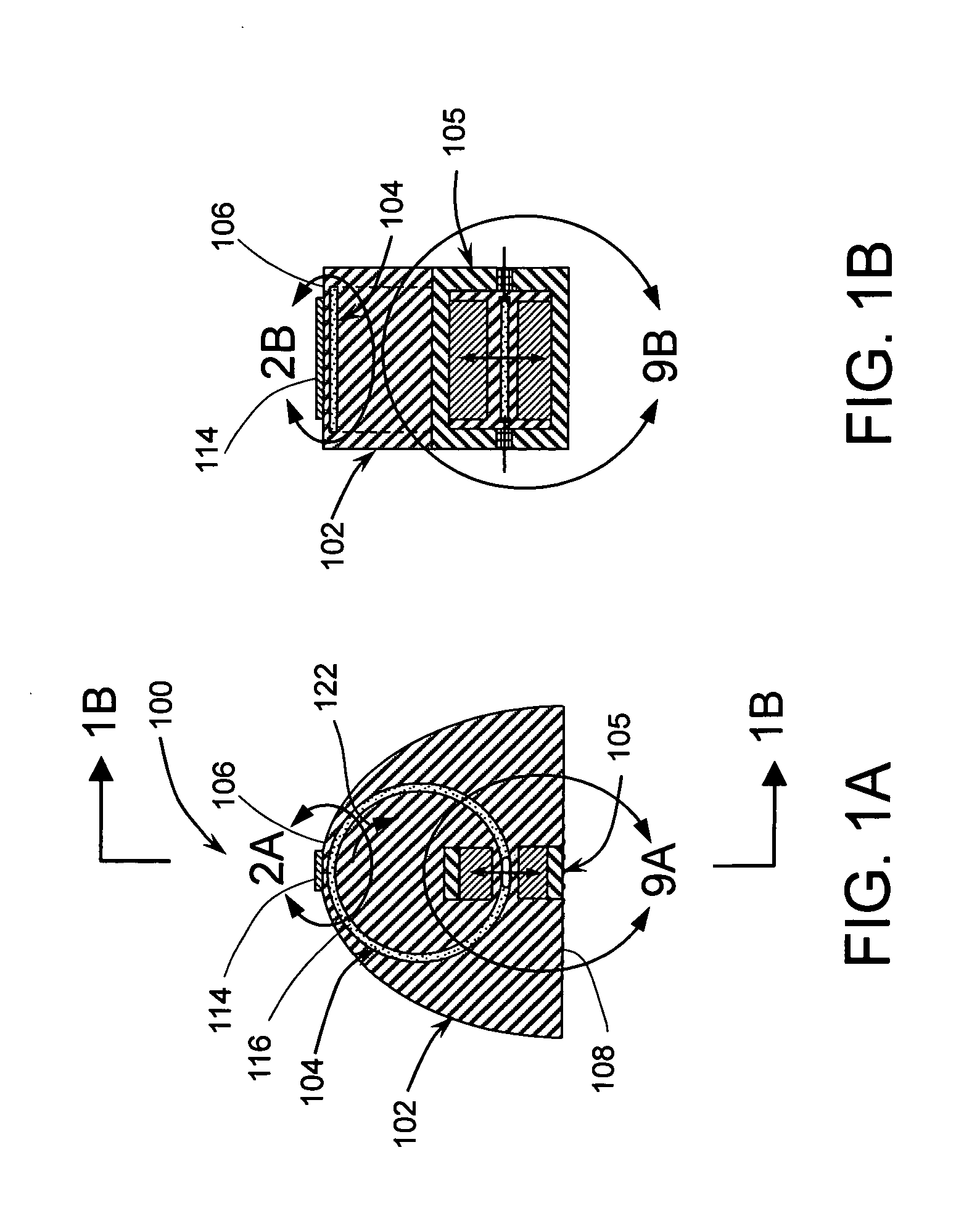
[0064]Referring now to FIGS. 1A and 1B, there is shown a heat transfer device (HTD) 100 in accordance with one preferred embodiment of the subject invention. HTD 100 may generally comprise a body 102 and a magneto-hydrodynamic (MHD) pump 105. The body 102 may further comprise a first surface 106 adapted for receiving heat from a heat generating component (HGC), a second surface 108 adapted for rejecting heat to a heat sink, and a flow channel 104. The body 102 may be preferably made of a material having high thermal conduc...


PUM


Abstract

The invention is for an apparatus and method for removal of waste heat from heat-generating components including high-power solid-state analog electronics such as being developed for hybrid-electric vehicles, solid-state digital electronics, light-emitting diodes for solid-state lighting, semiconductor laser diodes, photo-voltaic cells, anodes for x-ray tubes, and solids-state laser crystals. Liquid coolant is flowed in one or more closed channels having a substantially constant radius of curvature. Suitable coolants include electrically conductive liquids (including liquid metals) and ferrofluids. The former may be flowed by magneto-hydrodynamic effect or by electromagnetic induction. The latter may be flowed by magnetic forces. Alternatively, an arbitrary liquid coolant may be used and flowed by an impeller operated by electromagnetic induction or by magnetic forces. The coolant may be flowed at very high velocity to produce very high heat transfer rates and allow for heat removal at very high flux.

Description

CROSS-REFERENCE TO RELATED APPLICATIONS[0001]This application claims priority from U.S. provisional patent applications U.S. Ser. No. 61 / 339,198, filed on Mar. 1, 2010 and entitled “HEAT TRANSFER DEVICE;” U.S. Ser. No. 61 / 463,040, filed on Feb. 12, 2011 and entitled “THERMAL MANAGEMENT FOR SOLID-STATE HIGH-POWER ELECTRONICS,” and U.S. Ser. No. 61 / 463,210, filed on Feb. 14, 2011 and entitled “THERMAL MANAGEMENT FOR SOLID-STATE HIGH-POWER ELECTRONICS.” This patent application is a continuation-in-part patent application of: U.S. Ser. No. 12 / 290,195 filed on Oct. 28, 2008 and entitled HEAT TRANSFER DEVICE; U.S. Ser. No. 12 / 584,490 filed on Sep. 5, 2009 and entitled HEAT TRANSFER DEVICE; and U.S. Ser. No. 12 / 658,500 filed on Feb. 9, 2010 and entitled HEAT TRANSFER DEVICE; the entire contents of all of which are hereby expressly incorporated by reference.FIELD OF THE INVENTION[0002]This invention relates generally to a heat removal from heat-generating components and more specifically to...

Claims


Application Information

Patent Timeline
Patent Type & Authority Applications(United States)
IPC IPC(8): F28D15/00
CPCF28D15/00F28D15/02H01L2224/32225H01L2924/09701H01L23/473
Inventor VETROVEC, JAN
Owner VETROVEC JAN
Why Eureka
Try Eureka