Monitoring network based on nano-structured sensing devices

a nano-structured sensor and monitoring network technology, applied in the direction of optical radiation measurement, instruments, spectrophotometry/monochromators, etc., can solve the problems of unfavorable chemical molecule adsorption, weak scattering signal, additional hardware, etc., to enhance chemical molecule adsorption, enhance chemical specific binding, and enhance the effect of molecule surface binding efficiency

Inactive Publication Date: 2011-09-01
OPTOTRACE TECH
View PDF13 Cites 81 Cited by
  • Summary
  • Abstract
  • Description
  • Claims
  • Application Information

AI Technical Summary

Benefits of technology

[0020]Embodiments may include one or more of the following advantages. The disclosed systems and methods can effectively enhance chemical specific binding, to enhance molecule surface b

Problems solved by technology

Although Raman scattering is a useful analytical tool, it suffers a major drawback: the scattering signal is very weak due to the very small scattering cross section of molecules.
Of course, high power laser and high sensitivity CCD detector can be used to improve the scattering signals but coming with the extra costs, addit

Method used


Image

  • Monitoring network based on nano-structured sensing devices
  • Monitoring network based on nano-structured sensing devices
  • Monitoring network based on nano-structured sensing devices

Examples


example 1

Fabrication of Nano-Surface Arrays by Anodization Method

[0116]A thin film of Ti (about 100 nm) was deposited by e-beam evaporation of Si (100) wafer, followed by the deposition of Ag (about 100 nm). Then a 500 nm Al layer was deposited over the Ag film using physical vapor deposition method.

[0117]Then the coated Si wafer was placed into an anodizing bath with 0.3 M oxalic acid solution as the electrolytic solution. The bath was maintained at 10° C., and the anodizing voltage was set at 35 V. After anodization, nano-size narrow pores were formed in the Al2O3 layer. The diameter of the pores (or holes) can be widened by placing the wafer into a 10 wt. % phosphoric acid solution. The nano pore structure in the Al2O3 layer acted as a mask for etching active metal layer or depositing active metal layer. Thus a nano surface array was formed after removing oxidized Al layer.

example 2

Nanoimprint Lithography for Fabrication of Nano-Surface Arrays

[0118]The first step in nanoimprint is to press a mold into a thin resist cast on a substrate. The step is to duplicate the nanostructure on the mold in the resist film. The second step is to etch the resist film to form the nanostructure on the substrate.

[0119]The mold was patterned with an array of nano dots of 30 nm in feature size using electron beam lithography and reactive ion etching (RIE) on a Si wafer. PMMA was used as the resist on Au coated Si (100) wafer. A thin Ti layer was inserted between Au and Si to improve adhesive. The imprint process was carried out in vacuum at a temperate around 160° C., above the glass temperate of PMMA, at a pressure about 1000 psi. After the pattern from the mole was transferred to the Au coated Si (100), oxygen RIE was used to remove residue resist in the compressed areas in PMMA. Then, the pattern was etched into the Au film. After removing the PMMA, a nano-hole array was formed...

example 3

1) Demonstration of Nano Array

[0120]FIG. 24 is an example of scanning electron microscopy imaging of such nano surface arrays. The left image shows an array of nano-holes with 17 nm diameter and about 30 nm spacing. The image on the right shows an array of nano-holes with 38 nm diameter and about 10 nm spacing.

2) Demonstration of Surface Enhanced Raman Using the Nano-Surface Arrays

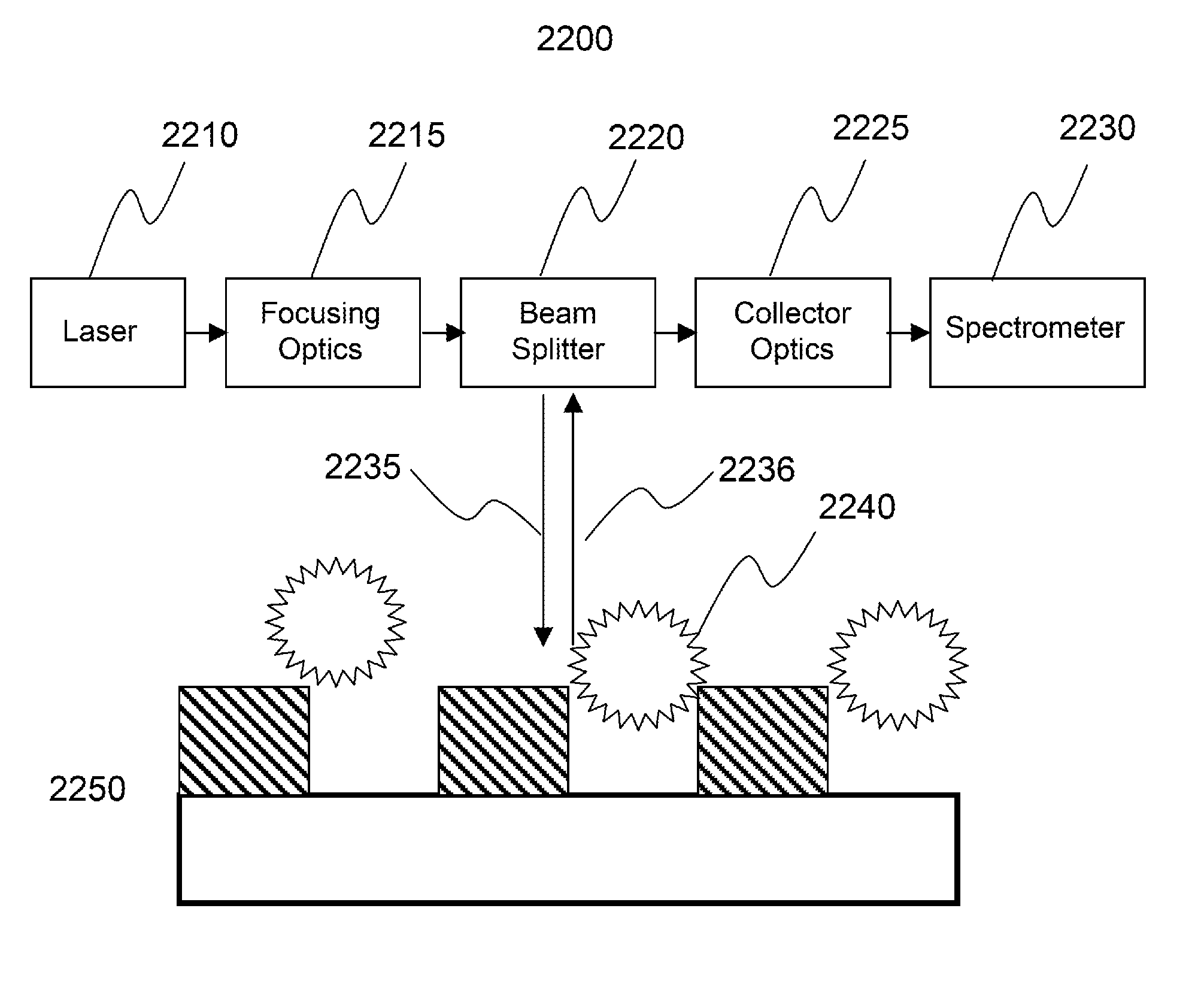
[0121]A Raman scattering system, as shown in FIG. 23B, includes a Raman nano-surface array on silicon, a semiconductor laser, which can collect the reflected lights on the surface. The sampling methods include: the array is placed in a solution container or a gas probe cell; or is just lie down horizontally, then to inject liquid chemical onto the surface; or the array is covered by a layer of glass or polymer without physical contact, liquid or gas sample is injected through a microfluidic channel.

[0122]FIG. 23C shows Raman spectra of xylenes. In this example, Raman spectrum of m-xylene, o-xylene, p-Xylen...


PUM


Abstract

A monitoring network system for inspecting and controlling harmful substances includes probe assemblies that each includes a sensor comprising nano structured surfaces or nano particles in a solution, configured to adsorb molecules of a sample material captured adjacent to the sensor, a laser that can emit a laser beam to illuminate the molecules adsorbed to the nano structured surfaces, a spectrometer that can produce spectral data from light scattered by the molecules adsorbed to the nano structured surfaces, and a ID reader that can retrieve identification information about the sample material. A central office can determine a spectral signature matching spectral signatures stored in a database and to identify a harmful substance in the sample material. An alert and response system can send out an alert signal about the sample material when the harmful substance is identified in the sample material.

Description

CROSS-REFERENCE TO RELATED APPLICATIONS[0001]The present application is a continuation-in-part application of and claims priority to commonly assigned pending U.S. patent application Ser. No. 12 / 502,903, filed Jul. 14, 2009, titled “Nano structured sensing device for surface-enhanced Raman scattering”, which claims priority to U.S. patent application Ser. No. 12 / 262,667, filed Oct. 31, 2008, titled “Arrays of nano structures for surface-enhanced Raman scattering”, which claims priority to U.S. patent application Ser. No. 11 / 562,409 (issued now as U.S. Pat. No. 7,460,224), filed Nov. 21, 2006. U.S. patent application Ser. No. 11 / 562,409 further claims priority to U.S. Provisional Patent Application 60 / 751,472, filed on Dec. 19, 2005. The present application is also a continuation-in-part application of and claims priority to commonly assigned pending U.S. patent application Ser. No. 12 / 625,970, filed Nov. 25, 2009, titled “Spectrally sensing chemical and biological substrates”, which...

Claims


Application Information

Patent Timeline
IPC IPC(8): C12M1/34G01J3/28G01J3/44G01N30/00B82Y15/00
CPCB82Y20/00G01N33/54346G01N21/658B82Y40/00G01N2021/3196
Inventor WANG, HONGLIU, CHUNWEI
Owner OPTOTRACE TECH
Why Eureka
Try Eureka