Method for manufacturing capacitor element

Inactive Publication Date: 2011-10-06
SHOWA DENKO KK
View PDF2 Cites 6 Cited by
  • Summary
  • Abstract
  • Description
  • Claims
  • Application Information

AI Technical Summary

Benefits of technology

[0029]According to the manufacture method of the present invention, oxygen in a dielectric coating film is prevented from diffusing, which allows the dielectric coating film not to have positive holes and defects even a

Problems solved by technology

However, a niobium oxide coating film obtained by chemically converting a niobium anode body is unstable compared to a tantalum oxide coating film.
It is thought that this encourage diffusio

Method used


Image

  • Method for manufacturing capacitor element
  • Method for manufacturing capacitor element
  • Method for manufacturing capacitor element

Examples


example 1

[0067]Niobium powder having an average primary particle diameter of 0.5 μm was prepared by ingot grinding, and polyisobutylmethacrylate dissolved in toluene was added to the niobium powder in an amount of 5% of the mass of the powder. The mixture was sufficiently stirred, followed by removal of toluene by evaporation. The obtained powder was molded with a tantalum powder molding machine, TAP-2R, manufactured by OPPC Co., Ltd., using a die of a 2.0 mm length and a 2.0 mm width together with a niobium wire having a diameter of 0.2 mm buried and implanted to obtain a powder molded product having an apparent green density of 3.0 g / cm3 and a mass of 22 mg.

[0068]The powder molded product was sintered at 1230° C. for 30 minutes under a reduced pressure of 5×10⁻⁴ Pa or less to produce a niobium sintered body. This sintered body had a CV value of 150000 μFV / g.

[0069]The niobium sintered body was immersed in an aqueous solution containing 3% by mass of phosphoric acid, 1% by mass of hydrogen p...

example 2

[0075]Commercially available niobium foil having a purity of 3 N and a thickness of 100 μm was cut into a piece of 10 mm×30 mm, and a niobium wire having a diameter of 0.2 mm was welded to a part of the short side of the piece. The piece was degreased with acetone, washed with nitric acid and then with water, and dried to obtain a niobium foil element.

[0076]The niobium foil element was immersed in an aqueous solution containing 3% by mass of phosphoric acid, 1% by mass of hydrogen peroxide and 25% by mass of ethylene glycol serving as a freezing point depressant, and the solution temperature was adjusted to −10° C. in a freezing equipment. The chemical conversion was performed by, first, increasing the voltage at a constant current and then maintaining a constant formation voltage for 120 minutes, 360 minutes, 480 minutes, or 600 minutes respectively. The chemical conversion was performed at a current density of 5.5 mA / cm2 or 0.83 mA / cm2 and a formation voltage of 60 to 300 V respec...

example 3

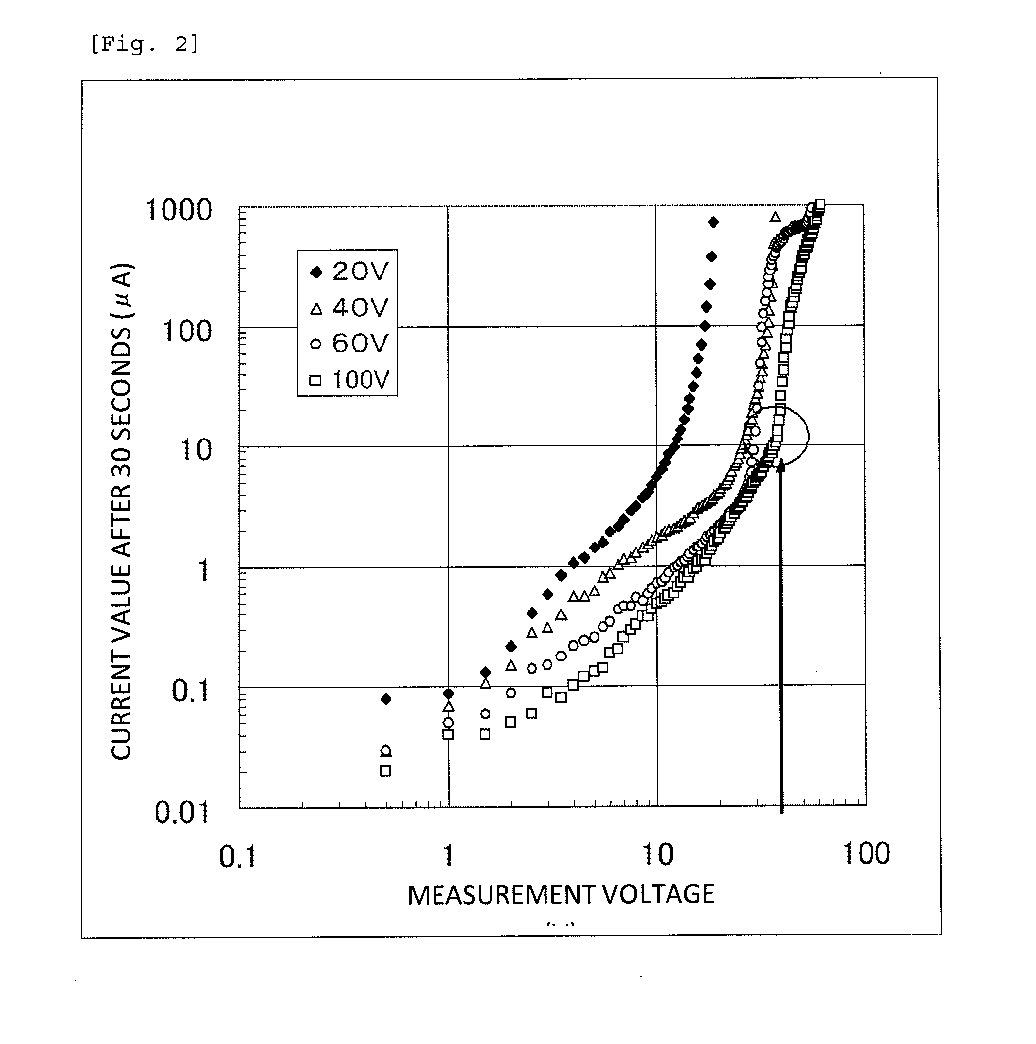
[0080]The capacitor element produced in Example 1, which was used as an anode, and platinum black, which was used as a cathode, were immersed in a 40% by mass sulfuric acid solution at room temperature, and a direct-current power supply was connected to the anode and the cathode in the forward direction. A direct current was applied between the anode and the cathode at a current of 10 mA and a voltage of 0.5 V, and the current value was measured after a lapse of 30 seconds from the start of the current application. The direct-current power source was switched off once, and a direct current was applied again at 1.0 V, which was higher than the voltage formerly applied by 0.5 V, and the current value was measured after a lapse of 30 seconds from the start of the current re-application. Similarly, the current values were measured on each time the voltage was increased by 0.5 V. FIG. 2 shows a relationship between the applied voltage values and the current values after a lapse of 30 sec...


PUM

PropertyMeasurementUnit
Electric potential / voltageaaaaaaaaaa
Temperatureaaaaaaaaaa

Abstract

A capacitor element is obtained by chemically converting an anode body comprising a niobium or niobium alloy in an electrolyte solution, which is obtained by dissolving an oxygen supply agent such as hydrogen peroxide, a freezing point depressant such as ethylene glycol, and an electrolyte such as phosphoric acid in water, at a solution temperature lower than the freezing point of a solution having the composition of the electrolyte solution excluding the freezing point depressant, for forming a dielectric layer in the surface of the anode body or repairing a dielectric layer formed in the surface of the anode body. An electrolytic capacitor is obtained by forming a cathode on the dielectric layer of the capacitor element, electrically connecting the anode body and the cathode respectively to external terminals, and then sealing them.

Description

TECHNICAL FIELD[0001]The present invention relates to a method for manufacturing a capacitor element. More specifically, the invention relates to a method for manufacturing a capacitor element having a niobium-base anode body that enables chemical conversion at a high voltage and suppresses a change in leakage current through a heat history, such as reflow, to be small.BACKGROUND ART[0002]In anode bodies of commercially available electrolytic capacitors, tantalum or aluminum is widely used. In the surface of such an anode body, a coating film (chemical conversion coating film) composed of an oxide of the anode material is formed by anodization (chemical conversion treatment). The chemical conversion coating film serves as the dielectric layer of the electrolytic capacitor. Since the performance characteristics of aluminum electrolytic capacitors highly differ from those of tantalum electrolytic capacitors, they are applied to different respective uses.[0003]In the meantime, niobium ...

Claims


Application Information

Patent Timeline
IPC IPC(8): H01G7/00
CPCH01G9/0032H01G9/07Y10T29/43Y10T29/417H01G9/15C25D11/26
Inventor SHIBUYA, YOSHINORISHIRAKAWA, AKIHIKOSUZUKI, MASAHIRO
Owner SHOWA DENKO KK
Why Eureka
Try Eureka