Method To Synthesize Colloidal Iron Pyrite (FeS2) Nanocrystals And Fabricate Iron Pyrite Thin Film Solar Cells

a technology of colloidal iron pyrite and nanocrystals, which is applied in the field of solar cells and nanocrystal-based solar cell devices, can solve the problems of limited market share and societal impact of cdte and cigs, and the inability to meet the large increase in energy demand by existing carbon-based technologies without further destabilizing the clima

Inactive Publication Date: 2011-10-06
RGT UNIV OF CALIFORNIA
View PDF6 Cites 33 Cited by
  • Summary
  • Abstract
  • Description
  • Claims
  • Application Information

AI Technical Summary

Benefits of technology

[0014]To develop an efficient p-n junction pyrite solar cell system, two exemplary methods of fabricating p-type pyrite thin film are presented. The first embodiment is directed to a method of synthesizing high-quality pyrite nanocrystal (NC) thin films from stable colloidal dispersions of single-crystalline, phase-pure pyrite NCs and then sintering the NC films in sulfur at moderate temperatures to produce large-grain polycrystalline pyrite films promising for the p-type pyrite thin film layer of p-n junction pyrite solar cell system. Pyrite NCs are of particular interest for low-cost solar energy conversion because of the prospect of fabricating inexpensive, large-area modules by the roll-to-roll printing or spraying of NC “solar paint” onto flexible metal foils. Nanocrystal-based devices can achieve excellent manufacturing scalability at lower cost ($ / Wp) than conventional single-crystal Si and existing thin film technologies.
[0015]The second embodiment is directed to a method of fabricating p-type pyrite thin film into high-quality, microcrystalline stoichiometric pyrite thin films by depositing microcrystalline pyrite onto a substrate layer by metal-organic chemical vapor deposition (MO-CVD). CVD is the best gas-phase process for depositing pyrite because it offers superior control of film morphology, purity and doping compared with alternative gas-phase methods (e.g., evaporation, sputtering, sulfurization of iron films, etc.).
[0017]One exemplary embodiment is directed to a method of manufacture of an efficient, low-cost p-n junction pyrite solar cell system from pyrite NC paints. Nanocrystalline pyrite films are made by dip coating, spraying, inkjet printing, or doctor blading the pyrite NC paint onto a substrate layer. These films are then sintered in special gas mixtures to yield stoichiometric polycrystalline pyrite films with carrier diffusion lengths that are significantly longer than the average optical absorption length. The surfaces of the films are then passivated chemically to increase the surface band gap and reduce the surface recombination velocity. A window layer is then deposited by chemical bath deposition (CBD), or other suitable deposition methods, such as atomic layer deposition (ALD), or chemical vapor deposition (CVD). The transparent top surface contact is then deposited by sputtering, CBD, ALD, or another suitable method.
[0019]To carry out the aforementioned methods of manufacture of an efficient, low-cost p-n junction pyrite solar cell system, exemplary embodiments of chemical passivation techniques are presented. Chemical passivation techniques are used to enhance photovoltage of p-type pyrite thin film to make them commercially useful for solar cells by eliminating iron-deprived gap states resulting from sulfur deficiency.
[0020]One embodiment of these chemical passivation techniques is directed to a method of passivating defect states within the bandgap of the p-type pyrite thin film by moderate-temperature annealing in S2, H2S, and H2 atmosphere. Another embodiment of these chemical passivation techniques is directed to a method of passivating defect states within the bandgap of the p-type pyrite thin film by coordination of surface iron with organic or inorganic ligands. A third embodiment of these chemical passivation techniques is directed to a method of passivating defect states within the bandgap of the p-type pyrite thin film by controlled alloying at the pyrite / window junction to grade the pyrite band gap and eliminate surface states.

Problems solved by technology

Such a large increase in energy demand cannot be met by the existing carbon-based technologies without further destabilizing the climate.
However, the future market share and societal impact of CdTe and CIGS PV will be limited by the scarcity of tellurium (Te) and indium (I) in the Earth's crust.
Most projections conclude that price constraints on tellurium and indium will limit CdTe and CIGS to 0.3 TWs or less of total solar conversion capacity, which falls far short of the tens of terawatts of carbon-free energy that are needed to meet the global energy challenge.
Subsequent progress in improving the efficiency of pyrite devices has been extremely modest.
The major limitation on the conversion efficiency of pyrite cells is the low open-circuit voltage, which typically does not exceed 200 mV (˜20% of the band gap) at room temperature.
The high quantum yield of sulfur-deficient pyrite suggests that bulk vacancies do not necessarily act as efficient recombination centers.
Nevertheless, a sufficiently high density of bulk vacancies will give rise to a defect band that decreases the band gap, and thus the photovoltage, of the material.
Relative to bulk defects, surface sulfur vacancies seem to have a more deleterious effect on the performance of pyrite devices.
Sulfur vacancies at the crystal surface also lead to FeS-like layers (which are quasi-metallic), oxides, and other defects that introduce additional traps and recombination centers, increase the dark current, and further reduce the photovoltage of pyrite samples.
The complexity of pyrite defect chemistry, combined with the low level of funding devoted to this material since the first demonstration of pyrite solar cells, explains why pyrite has not attained a more advanced level of development as a practical material for solar energy conversion, despite its great promise.

Method used


Image

  • Method To Synthesize Colloidal Iron Pyrite (FeS2) Nanocrystals And Fabricate Iron Pyrite Thin Film Solar Cells
  • Method To Synthesize Colloidal Iron Pyrite (FeS2) Nanocrystals And Fabricate Iron Pyrite Thin Film Solar Cells
  • Method To Synthesize Colloidal Iron Pyrite (FeS2) Nanocrystals And Fabricate Iron Pyrite Thin Film Solar Cells

Examples


first embodiment

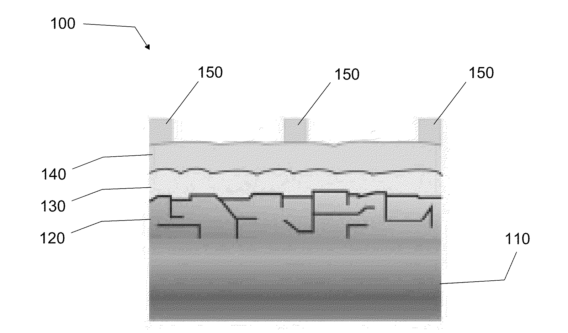
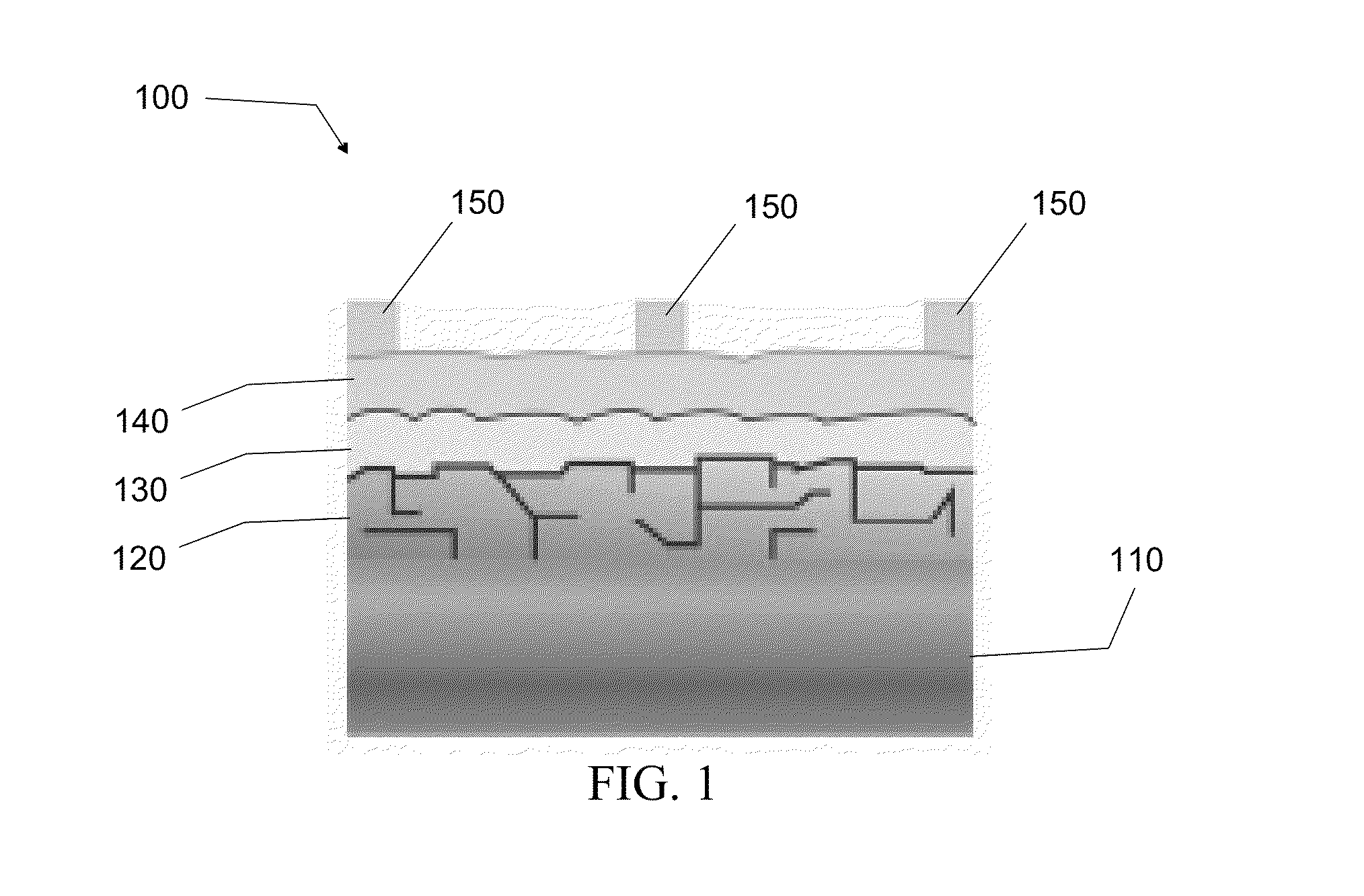
[0038]The first embodiment is directed to a method of synthesizing high-quality pyrite NC thin films from stable colloidal dispersions of single-crystalline, phase-pure pyrite NCs and then sintering the NC films in sulfur at moderate temperatures to produce large-grain polycrystalline pyrite films, which are promising for the p-type pyrite thin film 120 layer of p-n junction pyrite solar cell system 100.

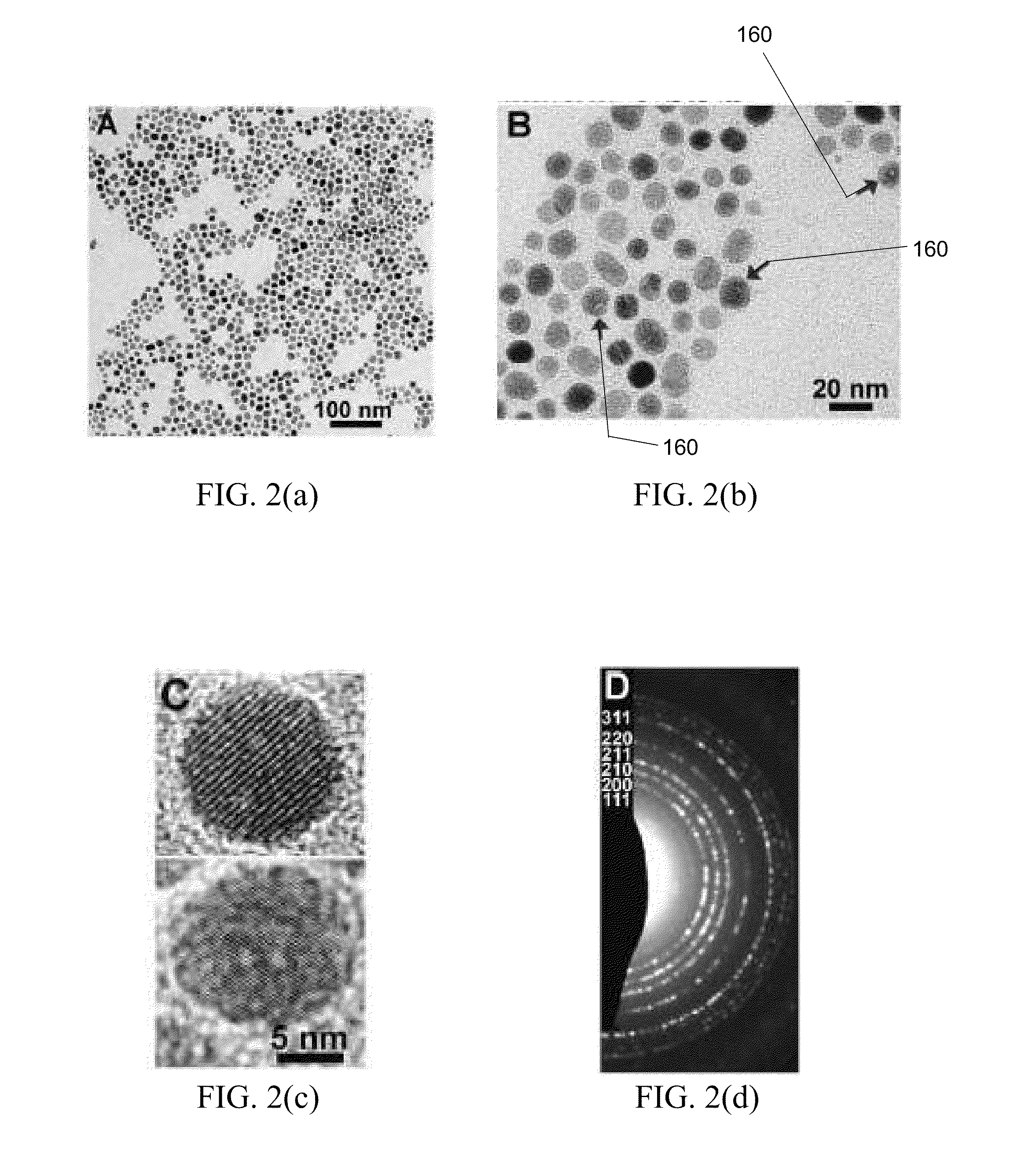
[0039]Pyrite NCs are of particular interest in low-cost solar energy conversion because of the prospect of fabricating inexpensive, large-area photovoltaics by roll-to-roll deposition of NC solar ink or paint on flexible substrates. NC-based photovoltaics processed from solution may offer excellent manufacturing scalability at very low cost compared to conventional single crystal and thin film approaches.

[0040]In one embodiment, colloidal pyrite NCs are synthesized by the following method. In a container, such as a three-neck flask, a reaction solution is created by mixing FeCl2.4H2O...

second embodiment

[0055]The second embodiment is directed to a method of fabricating p-type pyrite thin film 120 into high-quality, microcrystalline stoichiometric pyrite thin films by depositing microcrystalline pyrite onto substrate layer 110 by metal-organic chemical vapor deposition (MO-CVD). CVD is the best gas-phase process for depositing pyrite because it offers superior control of film morphology, purity and doping compared with alternative gas-phase methods (e.g., evaporation, sputtering, sulfurization of iron films, etc.). In a preferred embodiment, the substrate layer 110 is a metal foil. The use of a variety of different substrates, however, can serve as the substrate layer 110 in pyrite thin film 120. In particular, other flexible metal foil substrates (molybdenum, steel, aluminum, copper, etc.) that are electrically conductive can serve as the substrate layer 110 in p-type pyrite thin film 120. Other substrates such as glass and silicon can also serve as the substrate layer 110 in p-typ...


PUM

PropertyMeasurementUnit
temperatureaaaaaaaaaa
open-circuit voltageaaaaaaaaaa
diametersaaaaaaaaaa

Abstract

Systems and methods are provided for the fabrication and manufacture of efficient, low-cost p-n heterojunction pyrite solar cells. The p-n heterojunction pyrite solar cells can include a pyrite thin cell component, a window layer component, and a top surface contact component. The pyrite thin cell component can be fabricated from nanocrystal paint deposited onto metal foils or microcrystalline pyrite deposited onto foil by chemical vapor deposition. A method of synthesizing colloidal pyrite nanocrystals is provided. Methods of manufacturing the efficient, low-cost p-n heterojunction pyrite solar cells are also provided.

Description

CROSS-REFERENCE TO RELATED APPLICATIONS[0001]This application claims the benefit of provisional application Ser. No. 61 / 320,638, filed Apr. 2, 2010, which is fully incorporated herein by reference.FIELD[0002]The embodiments relate generally to solar cells and nanocrystal-based solar cell devices, and more particularly to iron pyrite thin film solar cell devices.BACKGROUND[0003]The current annual global energy demand of ˜14 terawatt-years (TW-yrs) is expected to double by mid-century and triple by the end of the century. Such a large increase in energy demand cannot be met by the existing carbon-based technologies without further destabilizing the climate. The sun is the largest source of carbon-free energy (120,000 TW-yrs strike the planet's surface annually) and can be used to produce both electricity and fuel. Yet in the United States, solar electricity (e.g. photovoltaics) and solar-derived fuels (e.g. biomass) currently provide about 1 millionth of the total electricity supply a...

Claims


Application Information

Patent Timeline
Patent Type & Authority Applications(United States)
IPC IPC(8): H01L31/06B05D3/04B05D3/02B05D3/12B05D5/12C23C16/30H01L31/0392C01G49/12B82Y40/00
CPCB82Y30/00B82Y40/00C01G49/12C01P2002/72C01P2004/03C01P2004/32Y02E10/50C01P2006/22C23C16/305C23C16/4417H01L31/032H01L31/072C01P2004/64B05D1/005B05D1/02B05D1/18C23C16/22C23C16/56
Inventor LAW, MATTSEEFELD, SEANPUTHUSSERY, JAMES
Owner RGT UNIV OF CALIFORNIA
Why Eureka
Try Eureka