
Material for organic electroluminescence device and organic electroluminescence device

a technology of electroluminescence device and material, which is applied in the preparation of isocyanic acid derivatives, organic chemistry, luminescent compositions, etc., can solve the problems of shortened device life, increased consumption power, and reduced efficiency, and achieves small steric hindrance, thermal stability, and maintain the effect of molecular planarity

Active Publication Date: 2011-11-10
IDEMITSU KOSAN CO LTD
View PDF0 Cites 5 Cited by
  • Summary
  • Abstract
  • Description
  • Claims
  • Application Information

AI Technical Summary

Benefits of technology

The invention is about a new material for an organic electroluminescence device that can be used in a hole-transporting layer. The material has an indenofluorenedone skeleton with specific properties that make it suitable for this application. The indenofluorenedone derivative has good electron acceptability, high crystallinity, and low driving voltage. It can also be used in a hole-injecting material and can suppress the formation of crystallization. The invention provides a new material that can help improve the performance of organic electroluminescence devices by reducing the voltage needed for operation and increasing the device's longevity.

Problems solved by technology

However, in order to attain sufficient luminance in an organic EL device in which these aromatic diamine derivatives are used as a hole-transporting material, problems such as shortened device life and increased consumption power occur, since an applied voltage is required to be increased.
However, the electron-accepting compound used in Patent Document Nos. 1 to 4 suffers from a problem in which it becomes unstable when handling during the production process of the organic EL device or the device life is shortened due to insufficient stability such as heat resistance at the time of driving of the organic EL device.
Therefore, it has a high sublimation property, and may diffuse within an apparatus when fabricating an organic EL device by vacuum vapor deposition, thereby contaminating the apparatus or the device.

Method used


Image

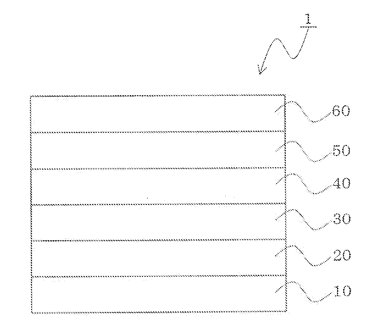
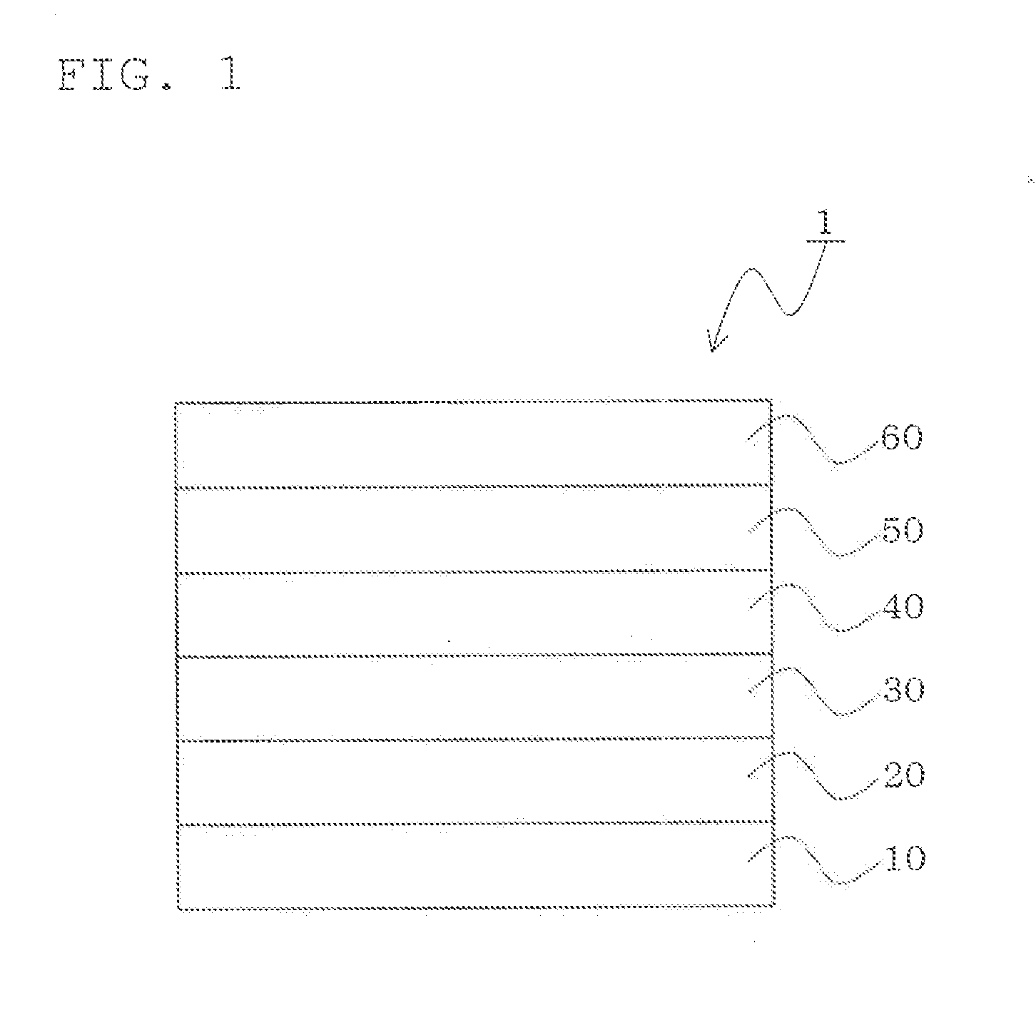
  • Material for organic electroluminescence device and organic electroluminescence device
  • Material for organic electroluminescence device and organic electroluminescence device
  • Material for organic electroluminescence device and organic electroluminescence device

Examples


example 1

[Synthesis of a Compound Shown by the Formula (A-1)]

[0200]The compound (A-1) was synthesized by the following synthesis scheme.

(1) Synthesis of Intermediate A

[0201]2.2 g of 3,9-dibromo-indenofluorenedione prepared according to a synthesis method described in a document (Organic Letters, vol. 7, issue 19, page 4229) was mixed with 2.1 g of 4-(trifluoromethyl)phenylboronic acid, 0.14 g of tris(dibenzylideneacetone)dipalladium (0), 0.091 g of tris-t-butylphosphine, 1.9 g of potassium fluoride and 40 ml of toluene under argon stream. The mixture was stirred with reflux for 8 hours. After cooling, the reaction liquid was filtered and a reddish purple solid was washed with water and methanol. As a result of mass spectroscopy of the resulting solid, a peak was observed at M / Z=570.

(2) Synthesis of Compound (A-1)

[0202]2.0 g of the intermediate A which had been synthesized before was dissolved in 100 ml of methylene chloride with stirring. After making the atmosphere of the inside of the flas...

example 2

[Synthesis of a Compound Shown by the Formula (A-2)]

[0207]

[0208]1.5 g of the intermediate A which had been synthesized before, 0.35 g of malononitrile and 80 ml of pyridine were added, and the resultant was heated with stirring at 90° C. for 8 hours. After cooling, the solid matter was filtered, washed with water and methanol, and dried under reduced pressure. Thereafter, purification through sublimation was performed to obtain 1.2 g of a purple crystal.

[0209]The IR of this compound was measured. The results showed that the absorption of a carbonyl group disappeared and the absorption of a cyano group was newly observed at 2222 cm−1. As a result of mass spectroscopy, a peak was observed at M / Z=666.

[0210]In the same manner as in Example 1, the reduction potential of this compound was measured by cyclic voltammetry. When the first oxidation potential of ferrocene (hereinafter referred to as the “Fc”) was taken as a reference potential, the reduction potential of the compound (A-2) was...

example 3

[Synthesis of a Compound Shown by the Formula (A-15)]

[0211]The compound (A-15) was synthesized from the compound shown by the following formula B.

[0212]In the synthesis of the compound (A-1) in Example 1, the same procedure was performed except that the intermediate A was changed to 1.1 g of the compound B, whereby 0.8 g of an orange solid as compound (A-15) was obtained.

[0213]The IR of this compound was measured. The results showed that the absorption of a carbonyl group disappeared and the absorption of a cyano group was newly observed at 2181 cm−1. As a result of mass spectroscopy, a peak was observed at M / Z=366.

[0214]The reduction potential of this compound was measured in the same manner as in Example 1 and found to be −0.7V (vs Fc+ / Fc).


PUM

PropertyMeasurementUnit
reduction potentialaaaaaaaaaa
transmittanceaaaaaaaaaa

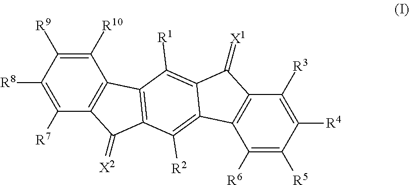
Abstract

A material for an organic electroluminescence device including an indenofluorenedione derivative shown by the following formula (I):wherein X1 and X2, which may be the same or different, are any of specific divalent groups; R1 to R10, which may be the same or different, are a hydrogen atom, an alkyl group, an aryl group, a heterocycle, a halogen atom, a fluoroalkyl group, an alkoxy group, an aryloxy group or a cyano group; and R3 to R6 or R7 to R10 may be bonded to each other to form a ring.

Description

TECHNICAL FIELD[0001]The invention relates to a material for an organic electroluminescence device and an organic electroluminescence device.BACKGROUND ART[0002]An organic electroluminescence device (hereinafter the term “electroluminescence” is often abbreviated as “EL”) is a self-emission device utilizing the principle that a fluorescent compound emits light by the recombination energy of holes injected from an anode and electrons injected from a cathode when an electric field is impressed.[0003]Since C. W. Tang et al. of Eastman Kodak Co. reported a low-voltage driven organic EL device in the form of a stacked type device, studies on organic EL devices wherein organic materials are used as the constituting materials has actively been conducted.[0004]The organic EL device reported by Tang et al. has a multilayer structure in which tris(8-hydroxyquinolinol)aluminum is used as an emitting layer and a triphenyldiamine derivative is used as a hole-transporting layer. The advantages of...

Claims


Application Information

Patent Timeline
Patent Type & Authority Applications(United States)
IPC IPC(8): C07D487/04C07C255/51C07D401/10C07C255/37C07C255/61C07C255/35
CPCC07C255/34H01L51/5012C07C261/04C07C2103/52C07D215/30C07D271/06C07D401/10C07D403/10C07D413/10C07D487/04C09K11/06C09K2211/1007C09K2211/1011C09K2211/1014C09K2211/1029C09K2211/1044H01L51/0051H01L51/0052H01L51/0053C07C255/35C07C2603/52H10K85/611H10K85/621H10K85/615H10K50/11C07C211/51H10K85/631H10K50/15H10K50/16H10K50/17
Inventor MORISHITA, HIRONOBU
Owner IDEMITSU KOSAN CO LTD
Learn More