
Phosphor member, method of manufacturing phosphor member, and illuminating device

a technology of phosphor and phosphor, which is applied in the direction of discharge tube/lamp details, discharge tube luminescnet screens, coatings, etc., can solve the problems of difficult control of resin dripping, high cost, and high cost, and achieve high environmental tolerance, high yield and extraction rate, and high heat resistance

Inactive Publication Date: 2012-01-26
KONICA MINOLTA OPTO
View PDF3 Cites 23 Cited by
  • Summary
  • Abstract
  • Description
  • Claims
  • Application Information

AI Technical Summary

Benefits of technology

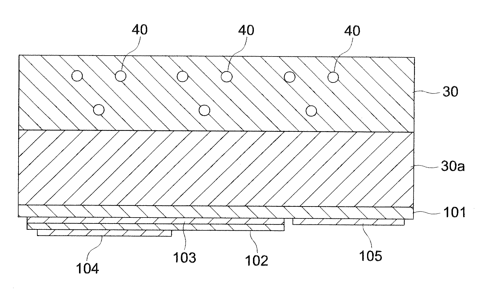
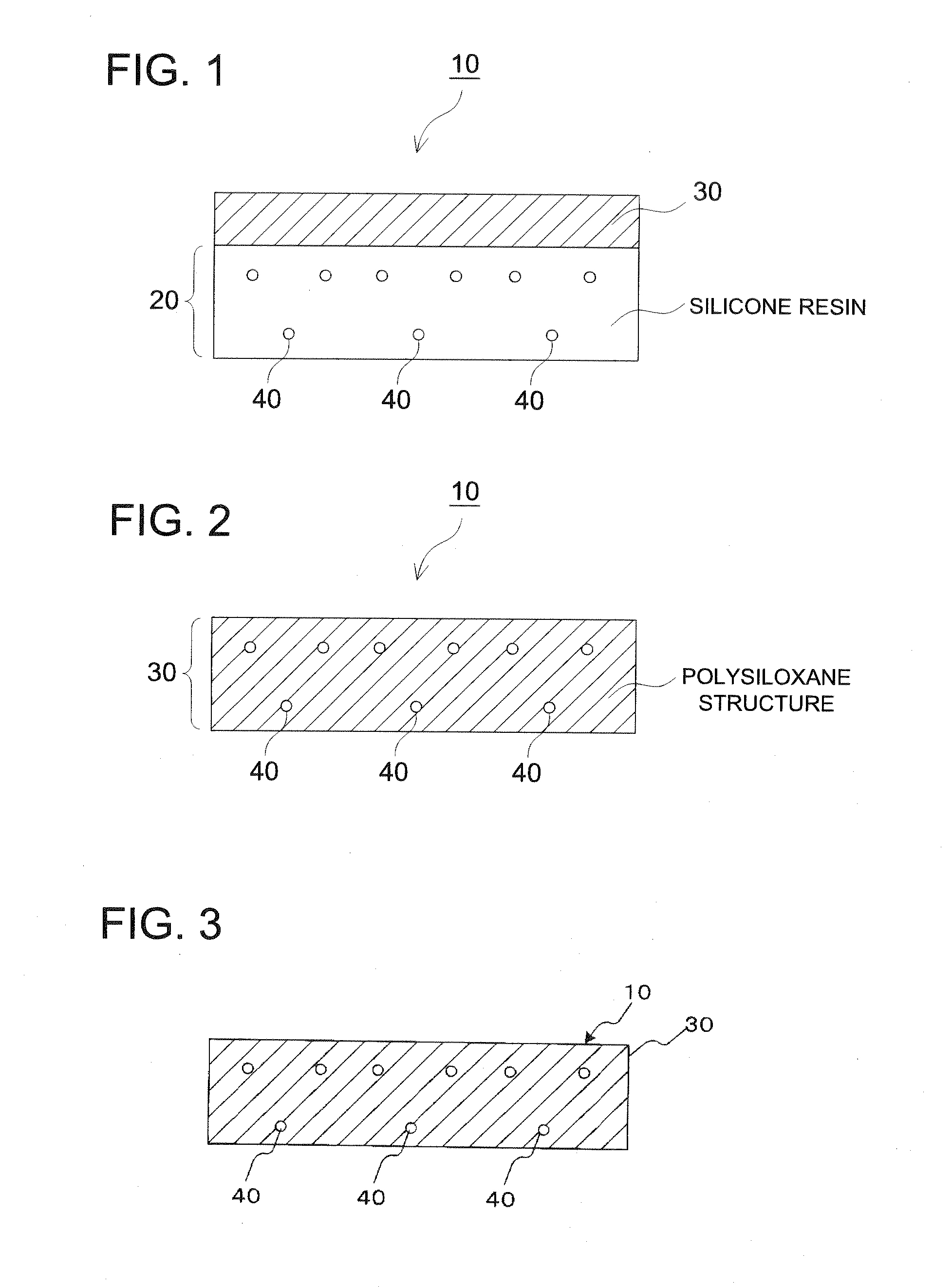
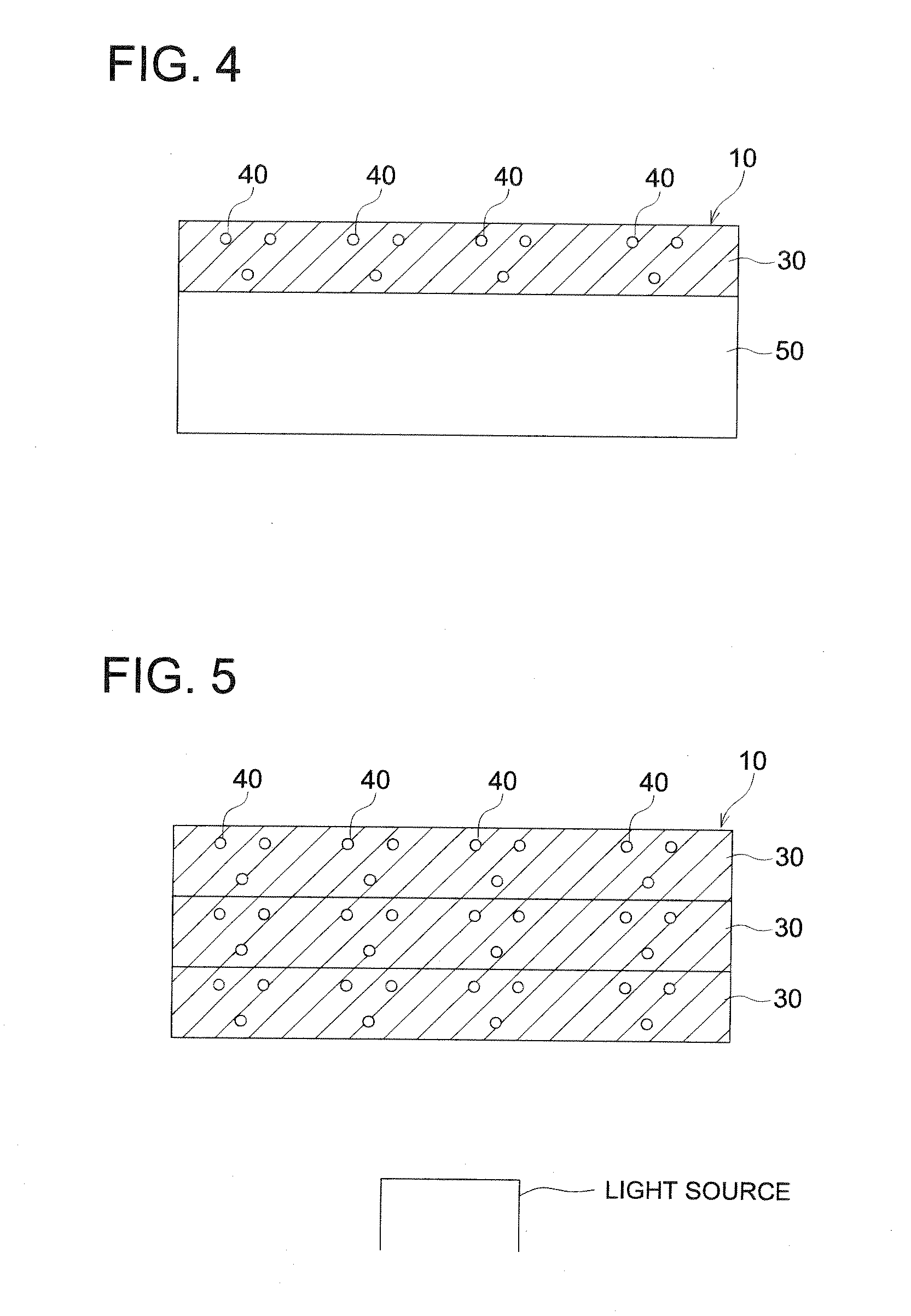
[0040]In the present invention, provided can be a phosphor member capable of improving a yield and an extraction rate, in addition to high environmental tolerance, high heat resistance, high durability and a high color rendering property, by which variations of color and an amount of light are reduced, and also provided a method of manufacturing the phosphor member and an illuminating device.

Problems solved by technology

However, a conventional method of forming a phosphor section in which a resin containing a phosphor, in an LED installation section produced a problem such that complicated processes consume too much time, since a small amount of resin containing a phosphor is dripped, filled and cured in each of LED installation sections.
Further, since it was difficult to control a dripping amount of resin, and a phosphor having a larger specific gravity than that of the resin appeared to tend to settle down within the curing time of the resin, differences were easily produced in settlement degree, and consequently, there appeared a problem such that color and an amount of light were largely varied in each light emitting section.
Further, a light-emitting diode enclosed by a protective resin containing the above-described phosphor, and further, in the case of the light-emitting diode entirely enclosed by s sealing resin, various practical problems are produced.
With respect to the first problem, when environmental tolerance of the protective resin and the sealing resin is not always sufficient, the phosphor blended in the protective resin is limited to a specific kind of the resin.
For example, a commonly known typical calcium sulfide based phosphor to be hydrolyzed by water content prominently produces such a problem.
Accordingly, since applicable phosphors were limited to specific kinds of them, there was a problem such as a poor color rendering property or the like.
Further, when employing a UV absorbent, since additional material to be used and operation processes are increased, there appears a problem such as rise in product prices.
Accordingly, there was a problem such as inferior environmental tolerance mainly to moisture resistance.
With respect to the third problem, because of turning yellow, and coloration of a coating resin exhibiting low heat resistance, there appears a problem such that light emitting from a light-emitting diode attenuates when its passing through a coating resin.
For example, a blue light-emitting diode chip formed of GaN (gallium nitride) having a high forward voltage exhibits large power loss even in the case of considerably low forward current, and largely increases chip temperature during operation.
It is commonly known that a resin is gradually degraded when it is heated to high temperature, resulting in turning yellow and coloration.
Accordingly, since when a light-emitting diode chip formed of GaN is used in a conventional light-emitting diode device, a resin gradually turns yellow and colors from a part brought into contact with a light-emitting diode chip at high temperature, the external appearance and emission intensity of the light-emitting diode device are gradually lowered In this way, in the case of a conventional light-emitting diode device, the above-described problem is produced when phosphor is blended with a resin.
For this reason, reduction of material kinds to be selected, drop in reliability, incompleteness in light conversion function, and rise in product prices result.
However, since an epoxy resin was used in a phosphor-sealing resin disclosed in the above-described Patent Document 1, the epoxy resin was optically degraded when using for a long duration, resulting in generation of a problem such as durability.
Further, since the resin turned yellow because of optical degradation, there appeared a problem such as a color rendering property.
As a result, wire disconnection tends to occur, whereby no long life can be expected, resulting in appearance of a problem such as durability.
Further, water content in the air is permeated to the inside of a silicone resin because of the silicone resin exhibiting high moisture permeability, whereby phosphor and a semiconductor layer appear to be often degraded, and there has appeared a problem such as environmental tolerance.
However, in the case of the phosphor sealing glass disclosed in the above-described Patent Document 3, since a heat resistance property is to be provided for phosphor, and the phosphor to he mixed in glass having been melt while heating is limited to specific kinds, fluorescence wavelength and efficiency lead to few options.
As a result, a color mixing ratio is difficult to be adjusted, and there appears a problem such as a color rendering property.
In the case of a chip disclosed in the above-described Patent Document 4, a semiconductor emitting element is sealed by putting glass in which phosphor is mixed into the cup section to be formed via solidification, but there has been a problem such that a yield and an extraction rate caused by semiconductor failure, failure of dispersing phosphor and emission failure are low.
It is difficult to evenly disperse phosphor particles in such a resin sheet, and when the phosphor particles were exccentrically located, and coagulated, there appeared a problem such that light taking-out efficiency to the outside was lowered because of light scattering, and a color rendering property was lowered when the light taking-out efficiency partially differs.

Method used


Image

  • Phosphor member, method of manufacturing phosphor member, and illuminating device
  • Phosphor member, method of manufacturing phosphor member, and illuminating device
  • Phosphor member, method of manufacturing phosphor member, and illuminating device

Examples


example 1

[0123]Four hundred grams of pure water was charged in a one liter stainless pot, and 600 g of silicon oxide 1 (product name: SPF-30M with an average particle diameter of 700 nm, produced by DENKI KAGAKU KOGYO KABUSHIKI KAISHA) were added therein, spending 5 minutes, at 6000 rpm, employing ULTRA-TURRAX T25 Digital (manufactured by IKA Works, Inc.), followed by dispersing for 30 minutes.

[0124]An operation, in which 1000 g of methylethyl ketone were added, and the solvent was removed at a vessel temperature of 40° C. and at reduced pressure of 26.6 kPa by an evaporator until the residual amount reached 800 g, was subsequently repeated 3 times, and finally, 200 g of methylethyl ketone were added to make the total weight to be 1000 g to obtain dispersion-1.

[0125]Next, 20 parts by weight of tetraethoxysilane {Si(C2H5O)3} and 80 parts by weight of nitrile ethoxysilane {C6H5Si(OC2H5)3} were mixed in 100 parts by weight of ethyl alcohol to produce reaction with a formic acid as a catalyst, a...

example 2

[0128]A sample in Example 2 was prepared similarly to the sample preparation of the above-described Example 1, except that dispersion-1 was replaced by the following dispersion-2.

[0129]Dispersion-2 was prepared similarly to preparation of the above-described dispersion-1, except that silicon oxide I (product name: SPF-30M with an average particle diameter of 700 nm, produced by DENKI KAGAKU KOGYO KABUSHIKI KAISHA) was replaced by silicon oxide 2 (product name: SPF-20M with an average particle diameter of 300 nm, produced by DENKI KAGAKU KOGYO KABUSHIKI KAISHA).

example 3

[0130]A sample in Example 3 was prepared similarly to the sample preparation of the above-described Example I, except that dispersion-1 was replaced by the following dispersion-3.

[0131]Dispersion-3 was prepared similarly to preparation of the above-described dispersion-1, except that silicon oxide 1 (product name: SPF-30M with an average particle diameter of 700 nm, produced by DENKI KAGAKU KOGYO KABUSHIKI KAISHA) was replaced by silicon oxide 3 (product name: SICASTAR with an average particle diameter of 70 nm, produced by Corefront Corporation).


PUM


Abstract

In the present invention, provided is a phosphor member capable of improving a yield and an extraction rate, in addition to high environmental tolerance, high heat resistance, high durability and a high color rendering property, by which variations of color and an amount of light are reduced, and also provided are a method of manufacturing the phosphor member and an illuminating device. Disclosed is a phosphor member prepared separately from an LED light source constituting a white illuminating device, wherein the phosphor member possesses phosphor particles and an inorganic layer having been subjected to coating and a heat treatment.

Description

TECHNICAL FIELD[0001]The present invention relates to a phosphor member, a method of manufacturing the phosphor member and an illuminating device in which the phosphor member is used, and specifically to a phosphor member prepared separately from an LED light source constituting a white illuminating device, which is to produce luminescence via wavelength conversion by absorbing a part of emission from an LED chip, and, and also to a method of manufacturing the phosphor member and an illuminating device in which the phosphor member is usedBACKGROUND[0002]In recent years, LED chips radiating blue light emitted by a gallium nitride based compound semiconductor, or UV radiation have been developed. Development of LED emitting devices emitting light with different hue from emission color of the chip including white color has been studied by using this LED chip in combination with various phosphors. This LED emitting device offers many advantages in small size, light weight and power cons...

Claims


Application Information

Patent Timeline
IPC IPC(8): H01L33/50B05D5/06B05D3/02H01J1/62
CPCH01L33/08H01L33/505H05B33/20H05B33/10H01L2933/0041C09K11/02C09K11/7774
Inventor HONDA, MIKA
Owner KONICA MINOLTA OPTO
Learn More