[0020]As described above, conventional X-ray tubes having a single focused electron beam impacting an X-ray emitting target may suffer from restrictions such as a limited
signal-to-
noise ratio and target overheating. The approach proposed herein includes the generation of a spatially structured electron beam using a structured electron emitter having a pattern of electron emission areas. Thereby, a
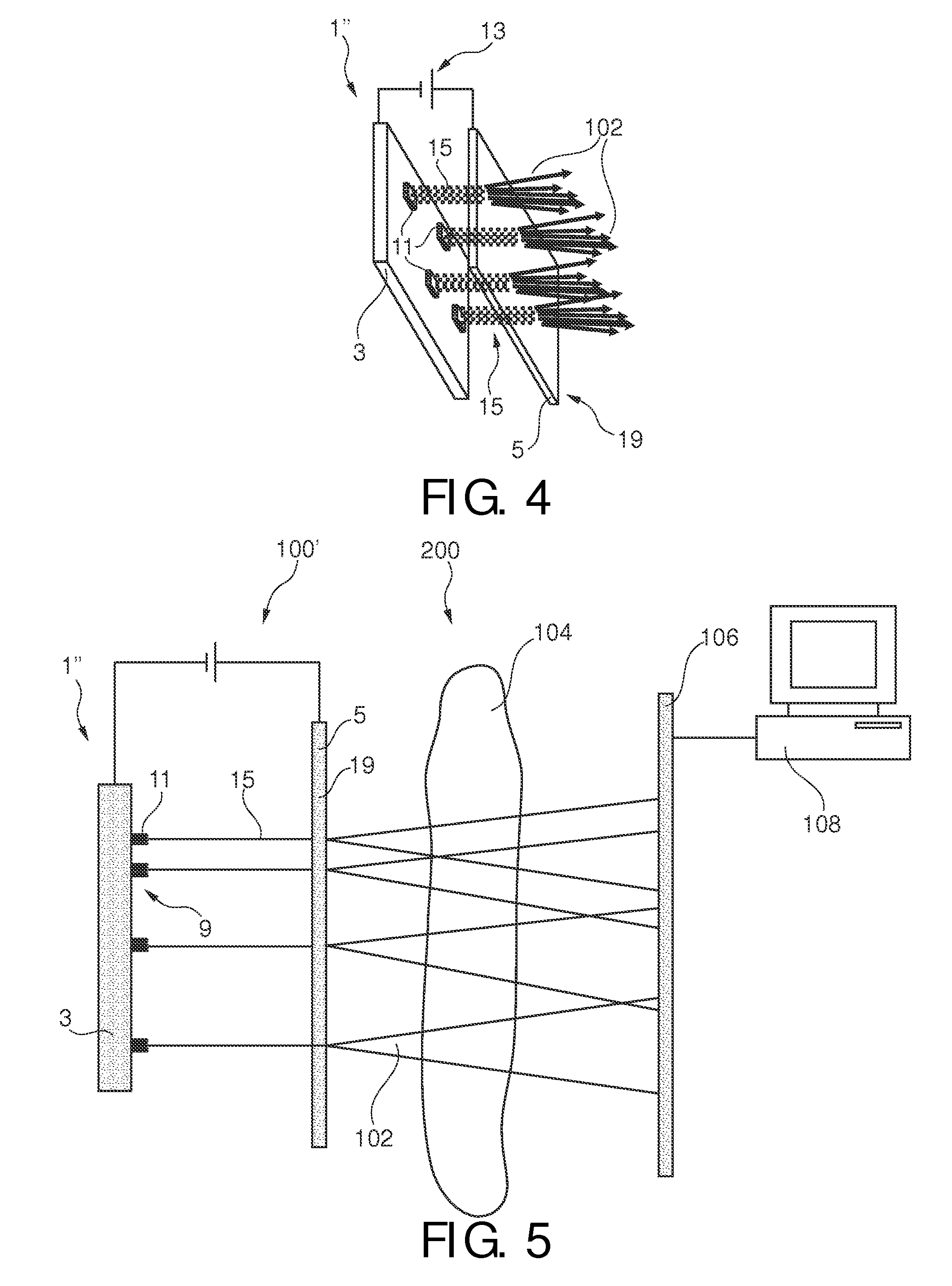
spatial modulation of an electron beam intensity can be achieved. For example, a multiplicity of separate electron beams can be emitted by the electron emitter, wherein each local electron emission area emits one confined electron beam. A spatially modulated overall electron beam comprising a multiplicity of separate sub-beams may be accelerated towards the anode and may create, upon
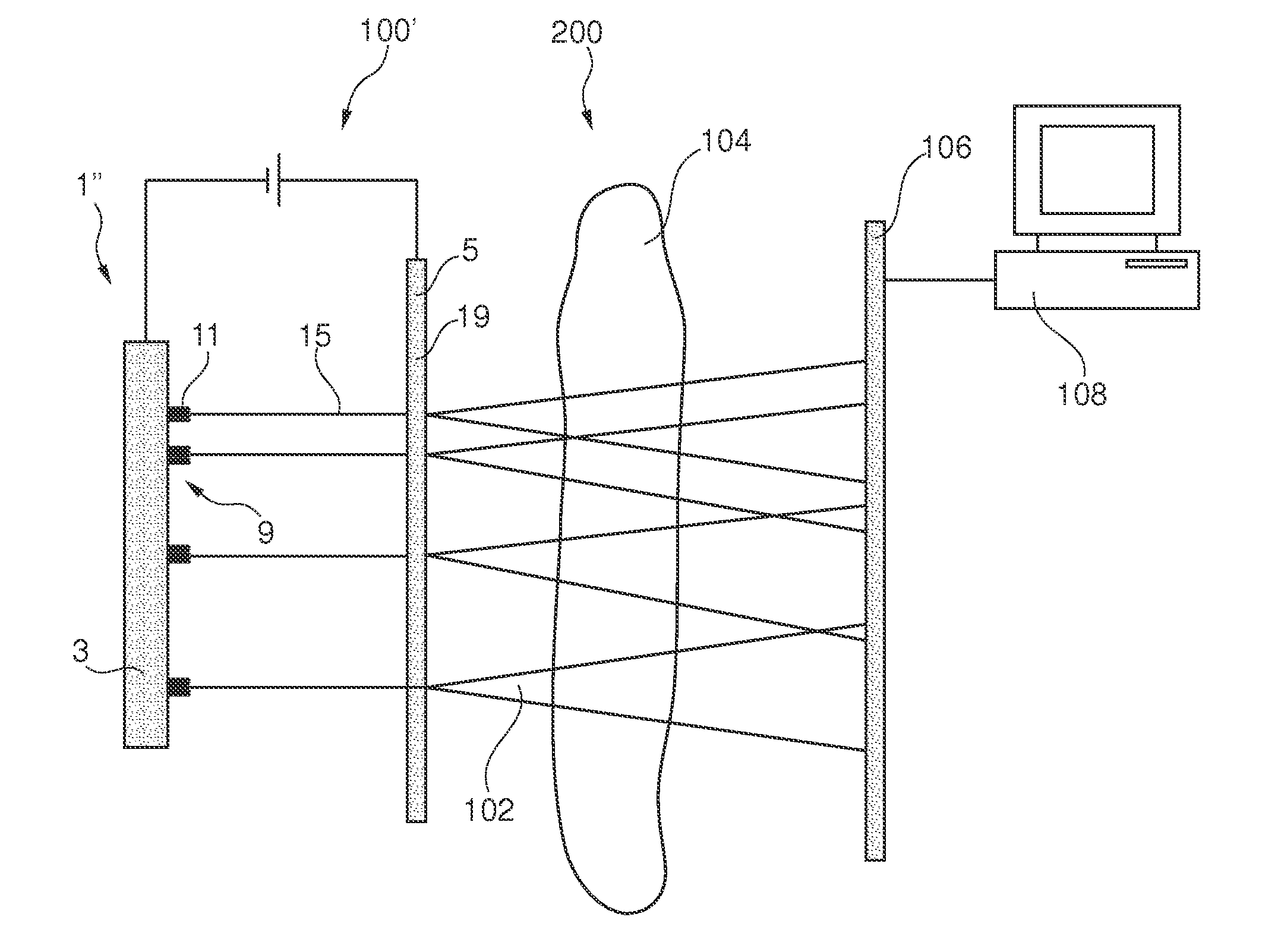
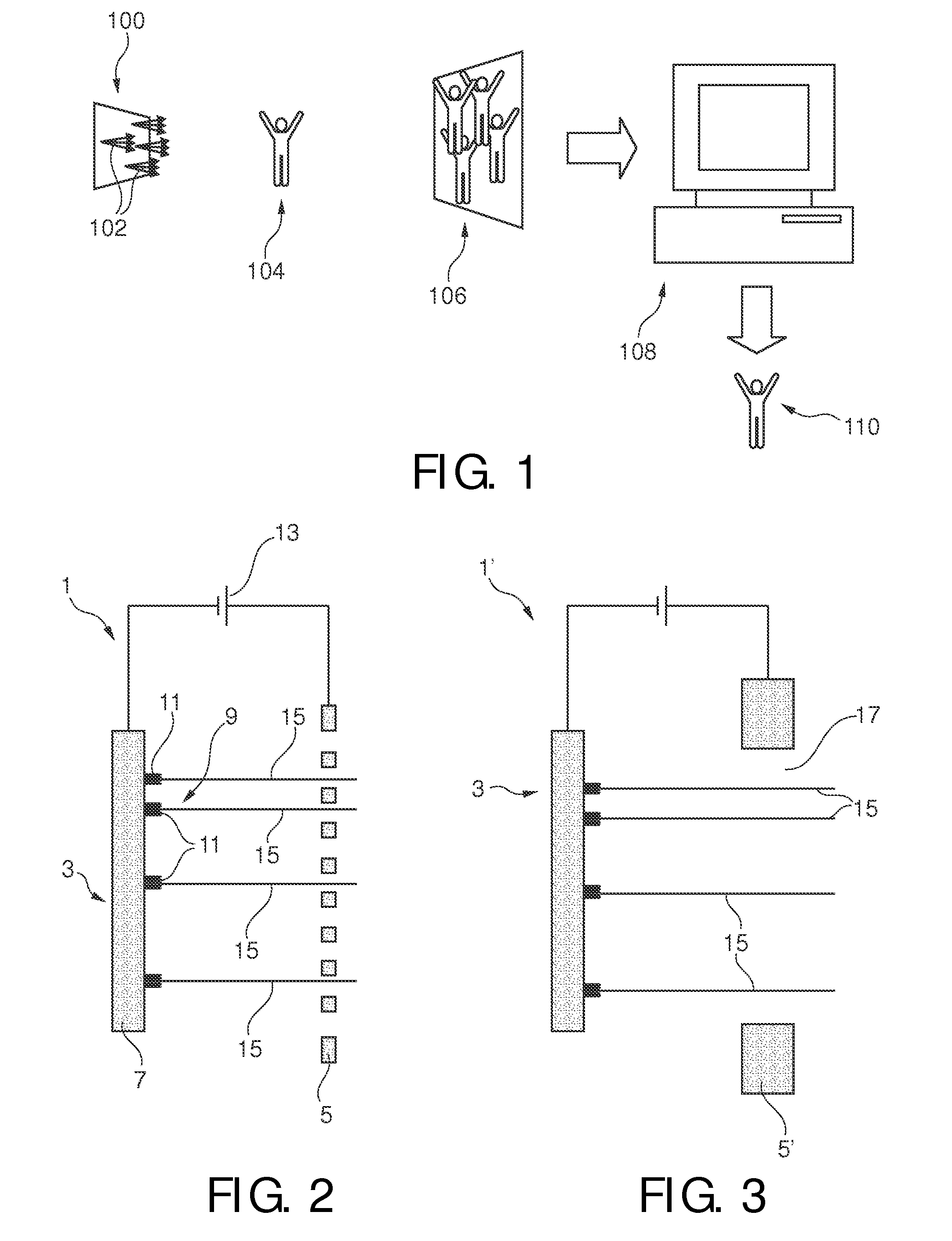
impact onto a target area, a patterned X-ray source having an X-ray intensity distribution corresponding to the intensity pattern of the electron beam. Thus, the created patterned X-ray source may be used for coded
source imaging wherein each of the X-ray intensity maxima may serve as a separate X-ray source. The X-rays of the combination of all X-ray sources may then be transmitted through an object to be observed. The transmitted X-ray intensities can be detected by an X-ray
detector. The detected X-ray intensity distribution may correspond to overlapping X-ray projections from each of the multiplicity of separate X-ray sources provided by the X-ray tube. From the detected X-ray intensities, an image of the object to be observed can be derived using information of both, the detected intensity distribution as well as the electron emission pattern of the electron emitter. Knowing exactly the pattern of the local electron emission areas in the electron emitter may provide information on the X-ray intensity distribution of the X-ray tube in which electrons coming from the local electron emission areas are projected onto a target area. This information on the patterned X-ray intensity distribution may be used to “decompose” or “deconvolute” the measured transmitted total X-ray intensity distribution, thereby allowing the generation of a high quality X-ray image in which the resolution is mainly set by the size of an isolated intensity maximum and not by the envelope of the overall X-ray source intensity distribution.
[0021]In other words, by using a structured source of electrons, multiple intensity maxima of X-rays with a specific pattern can be generated, which contribute to the
image signal without compromising
image quality. Therefore, the electrons can impinge on a larger region in the target area which may relax the thermal limitations. This may allow an increase of X-ray output thus enabling
image acquisition within a shorter time and having a better
signal-to-
noise ratio.
[0032]According to an embodiment, the local areas on the cathode of the electron emitter are provided with a microscopically
rough surface. This
rough surface may be adapted for maximizing the electron emission current generated by field emission from the local areas. As already indicated above, field emission may be a result of
quantum mechanical tunnelling of electrons through the surface potential barrier of the bulk into
free space. The number of field emitted electrons is strongly dependent on the local electrical field E [V / m] at the corresponding surface. The
field emission current can be increased by using a
rough surface including sharp conducting pins, since at small structures, a strong enhancement of the
local field strength may occur. In a
diode-type arrangement, the
electric field is generated by a
voltage applied between the cathode and an opposing anode. The macroscopic field can be approximately quantified by the
voltage U and the distance d and amounts to U / d. Locally, the strength of the
electric field near the emitter may vary from U / d, since the macroscopic field may induce a charge distribution. The field enhancement may depend on the geometrical form of the field emitter and the geometrical arrangement of adjacent field emitters. Quantitatively, the field enhancement maybe described by a field enhancement factor γ, such that the electrical field is E=γ(U / d).
Electron emitters based on field emission may benefit from such field enhancement as it reduces the external
voltage needed to create a
local field which provides sufficient field emission. Preferably, the field emitters have a conical form with a very narrow tip as such a geometrical shape leads to
strong field enhancement.
[0036]MWNTs may have several prominent characteristics. They may be good electrical conductors and their high
aspect ratio and
low work function of about 5 eV making them good candidates for field emission. As their walls are made of a very strong
graphite structure, they may have also a high
mechanical strength and furthermore they are chemically rather
inert and sputter-resistant. These characteristics may be advantageous to achieve the desired lifetime for electron emitters in X-ray tubes. The high
mechanical strength may allow to produce a field emitter with a
large aspect ratio, i.e. a large ratio of length and
diameter. This may lead to an advantageous field enhancement factor. For the
surface layer of CNT emitters different surface morphologies may exist. Singly isolated tubes may be arranged on the surface, where all tubes are aligned with respect to each other and the distance between individual CNT can be much larger than their length. Alternatively, CNTs may be densely arranged adjacent next to each other either in an array or with random orientation of the tubes with respect to each other. Depending on the surface morphology, selected CNT will protrude above the surface thus experiencing a stronger effect of field enhancement. These CNT emitters may predominantly contribute to the electron emission current.
[0037]The contributing CNT emitters preferably have a lateral distance to an adjacent neighbour in order to avoid shielding which would reduce the field enhancement. However, a sparse density reduces the number of contributing CNT emitters per unit area. Therefore there is an optimal distance between elevated CNT emitters which maximizes the
field emission current. As in the case of CNT emitters the preferable distance between field emitting pins is preferably two times as large as their height above the surface areas which do not or only minimally contribute to field emission.

