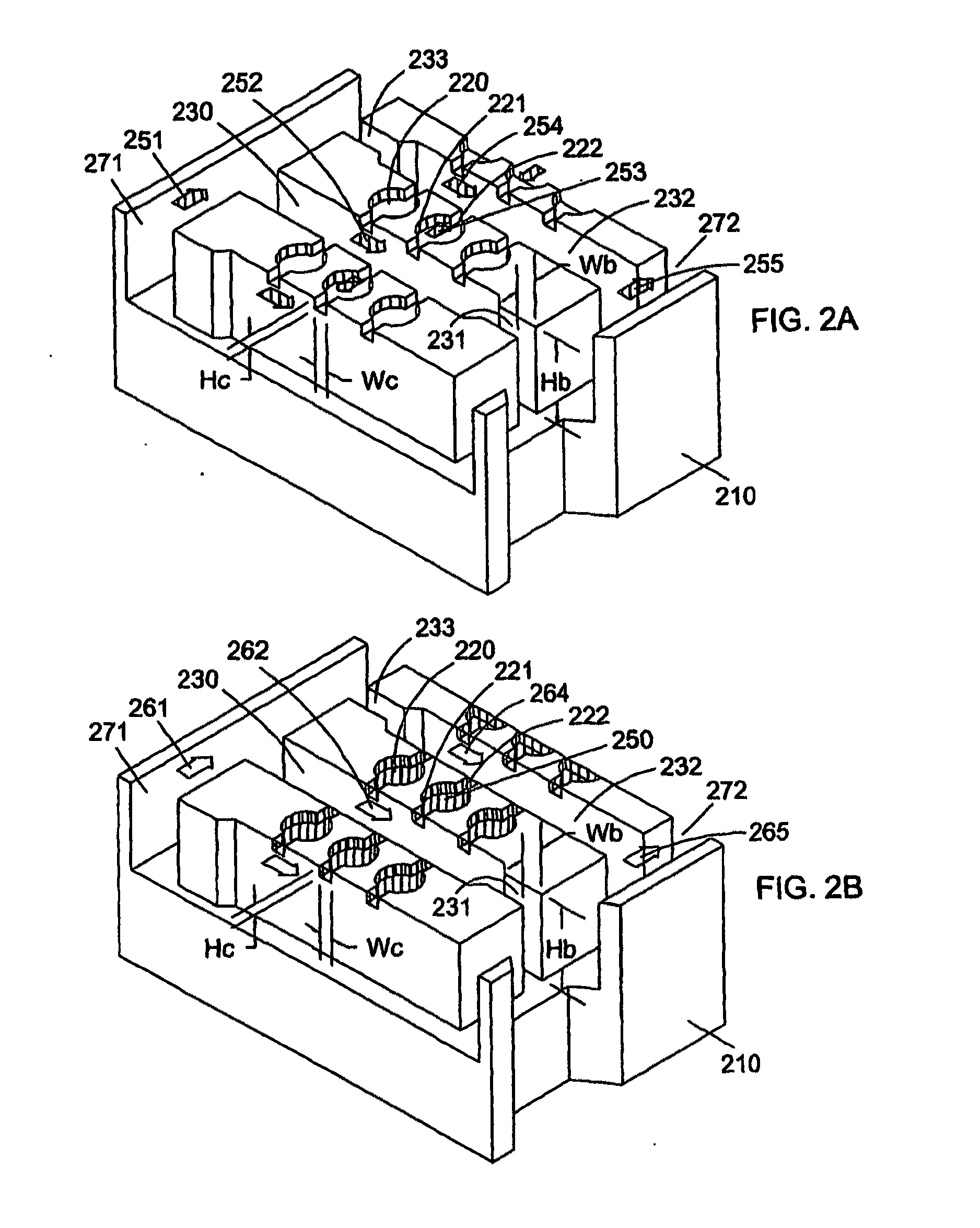
[0150]Another
advantage of the present invention is the ease of bubble and particle removal from the disclosed microfluidic array devices. For most of applications, the bypass channels 231 and 232 of FIG. 2 have significantly larger cross-sections than that of inlet and outlet conduits 221 and 222. These bypass channels, therefore, provide easier paths for particles and bubbles to be flushed out the device.
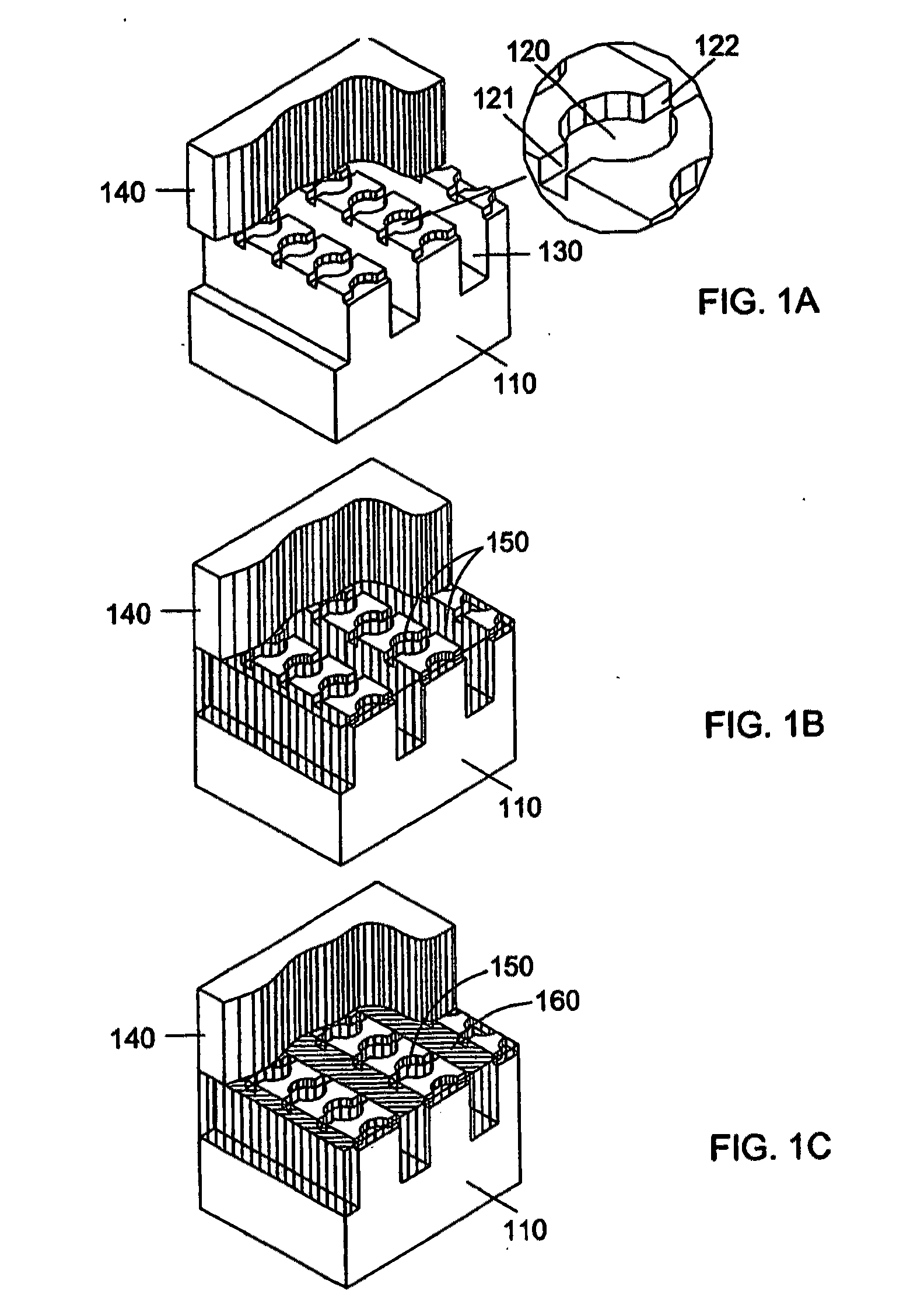
[0151]In another aspect of this invention, the cover plate 140 is a flat and opaque or translucent plate. The
optical transparency of the cover plate 140 is not necessary when a chamber array device shown in FIG. 1A is to be used as a
multiplexing reactor for non-photochemical reactions and a non-photo-detection based
assay device. Non-photochemical reactions include electrochemical reactions, which have been described by Montgomery in U.S. Pat. No. 6,444,111. By adding electrodes to the chamber array device, one skilled in the art of
electrochemistry may perform
multiplexing synthesis reactions. An exemplary non-photo-detection based assay is the
electron transfer based
nucleic acid detection, which is described by Meade et al. in U.S. Pat. No. 6,013,459 and the references therein. By adding electrodes in a chamber array device, one skilled in the art of molecular electronic detection may perform multiplexing
nucleic acid and other molecular detection.
[0152]Another preferred variation of the present invention is the use of a
microwell plate to perform hybridization-
PCR assay. In a preferred embodiment a
microwell plate contains a plurality of microwells of 1 to 500 microns in
diameter and 1 to 500 microns deep. The plate can be made of glass,
silicon, plastic, and any other appropriate materials. The fabrication of such a plate is well-know to those skilled in the art of
microfabrication (Gao et al. U.S. Pat. No. 6,426,184). In a preferred embodiment, the
microwell plate is assembled with an
enclosure to form a fluidic device which contains inlet and outlet to allow fluids to be injected and / or circulatted. An exemplary make and use of a glass-based microwell plates is described by Leproust et al. in “Digital light-directed synthesis. A
microarray platform that permits rapid reaction optimization on a combinatorial basis”, J. Comb. Chem. 2, 349-354 (2000). For real-time PCR application, the bottom of the wells is covalently deposited with probe molecules containing primers and binding probes. In a preferred embodiment, the interior surface of the microwells is hydrophilic and the outside surface of the microwells hydrophobic. In an illustrative assay process, a solution containing DNA sample sequences is first circulated through the fluidic device at a proper temperature so that those sample sequences complimentary to respective binding probes would be hybridized and retained in the corresponding microwell while non-specific sample sequences would not be retained. A brief wash with a suitable
buffer solution will then be applied to the fluidic device at a reduced temperature to wash the non-specific sample sequences out of the device while keeping the hybridized sample sequences in the microwells. A PCR mix based on
SYBR Green I double-stranded DNA binding dye assay is then be injected into the device. As described in the above paragraphs, the PCR mix contains RNase A or other appropriate cleavage reagents. To avoid premature cleavage,
chip temperature will be kept low (e.g. at 4° C.) when the PCR mix is injected into the device. An isolation fluid, such as oil or an
inert gas, is then injected into the
chip to isolate all the microwells and real-time PCR reaction is carried out thereafter.
[0153]Another alternative form of microwell plates is to facilitate a different isolation mechanism. Each microwell has an extruded lip. The microwells can be sealed or isolated by pressing an
elastomer sheet or a laminate film having an
adhesive coating against the microwells. The extruded lip helps the seal. The
elastomer and the laminate film can be selected from various materials that are compatible with the temperatures used in PCR processes, chemically
inert, and of low
fluorescence.
[0154]Another aspect of the present invention is the use of beads within the fluidic device to significantly increase the synthesis capacity of the device for parallel synthesis applications. In a preferred embodiment the beads are made of high-loading substrate materials including but not limited to partially crosslinked and
functionalized polystyrene beads, crosslinked
polystyrene-PEG
copolymer beads, CPG, and various other commonly used and specialized resin material used in
solid phase synthesis. In a preferred embodiment, all beads are substantially spherical and of narrow size distribution. A fluidic device similar to that shown in FIG. 2A, except the structure of the reaction chambers, is used. In one aspect of the present invention the outlet side of each
reaction chamber contains a barrier to stop beads from passing through and allow liquid to flow through. The bypass channels should be wide enough to allow beads to pass through so as to avoid plugging of the transport channels by the beads. Before loading the beads into the reaction chambers, the beads are suspended in a liquid having substantially the same density as that of the beads (excluding the void inside the beads). Then, the bead suspension liquid is circulated through the fluidic device till all the reaction chambers are filled with the beads. The process of using the bead-loaded fluidic device for
chemical synthesis is similar to that of a regular device as what is described in the above paragraphs.
[0155]FIG. 10 schematically illustrates a bead-containing
chip. For illustration purpose, only a 1D array is shown. A 2D array, which is the format of a real chip, can be constructed by repeating the 1D structure in the y direction. During an operation, the fluid enters the chip through a main
inlet channel 1071, splits and flows into inlet transport channel 1030, further splits and flows through
reaction chamber 1020, merges into outlet transport channel 1032, and further merges into a main outlet channel 1072 and flows out of the chip. A portion of the incoming fluid reaches the main outlet channel 1072 through inlet or outlet bypass channels 1031 and 1033 without passing through any reaction chambers 1020 or the inlet transport channel 1030. The function of the bypass channels 1031 and 1033 will be described later. The main considerations in the design of this chip include fluid flow distribution, synthesis capacity, bead-loading mechanism, chemical and photochemical reaction efficiency, device fabrication, and production cost.

