

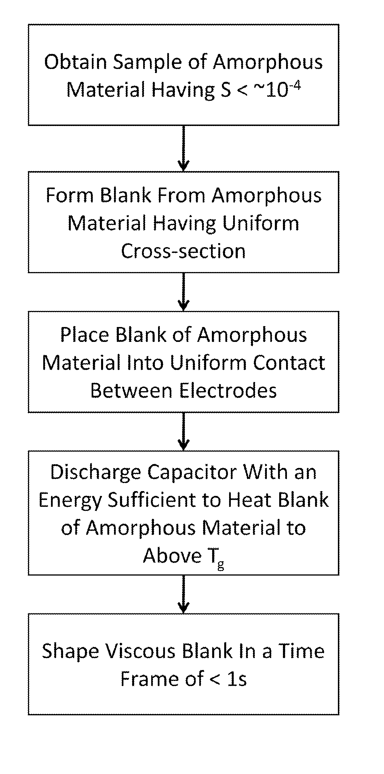
Forming of metallic glass by rapid capacitor discharge forging
- Summary
- Abstract
- Description
- Claims
- Application Information
AI Technical Summary
Benefits of technology
Problems solved by technology
Method used
Image

Examples
example 1
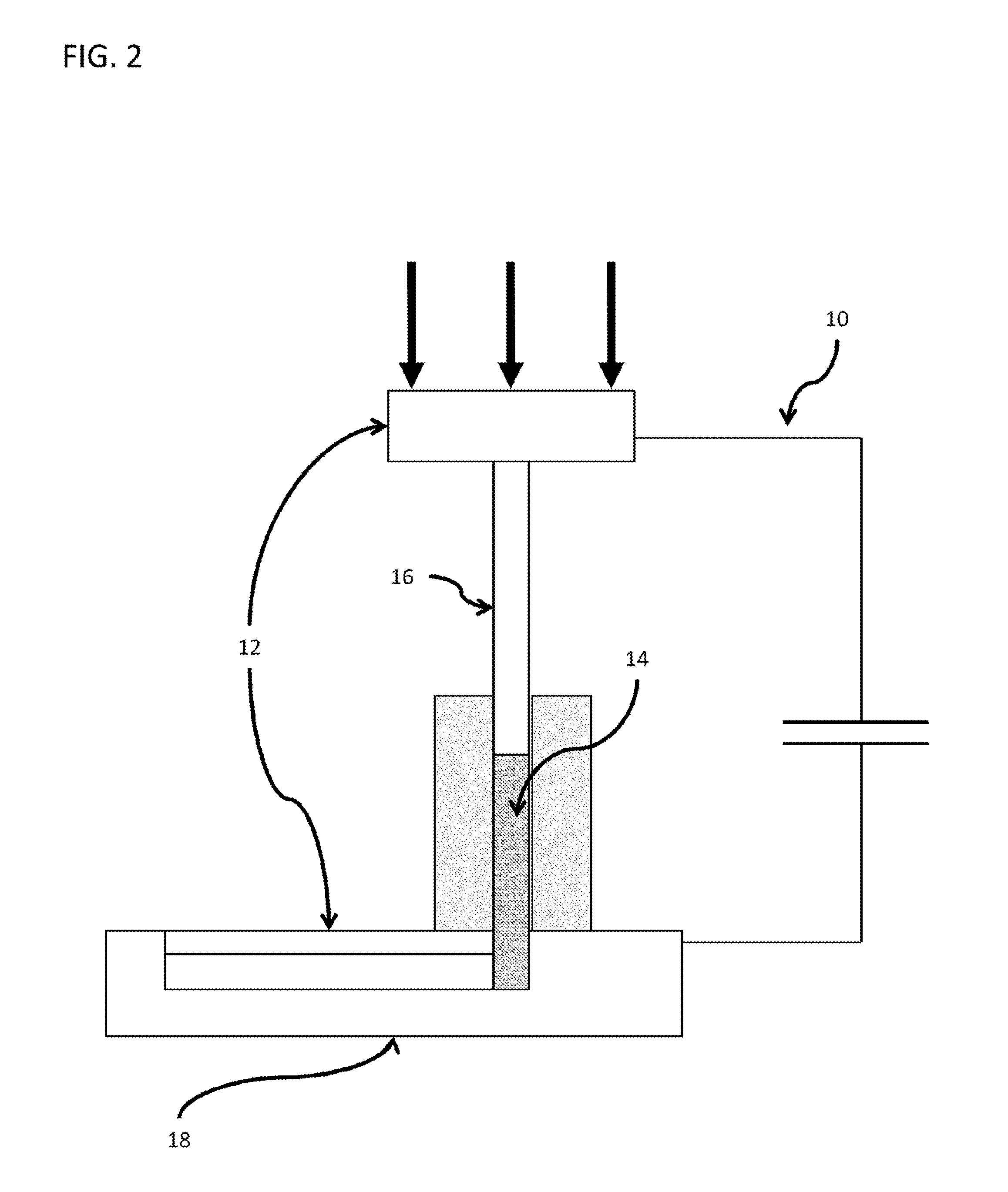
Study of Ohmic Heating
[0091]To demonstrate the basic principle that for BMGs capacitive discharge with Ohmic heat dissipation in a cylindrical sample will give uniform and rapid sample heating a simple laboratory spot welding machine was used as a demonstration shaping tool. The machine, a Unitek 1048 B spot welder, will store up to 100 Joules of energy in a capacitor of ˜10 μF. The stored energy can be accurately controlled. The RC time constant is of order 100 μs. To confine a sample cylinder, two paddle shaped electrodes were provided with flat parallel surfaces. The spot welding machine has a spring loaded upper electrode which permits application of an axial load of up to ˜80 Newtons of force to the upper electrode. This, in turn permits a constant compressive stress ranging to ˜20 MPa to be applied to the sample cylinder.
[0092]Small right circular cylinders of several. BMG materials were fabricated with diameters of 1-2 mm and heights of 2-3 mm. The sample mass ranged from ˜40...
example 2
Injection Molding Apparatus
[0096]In another example, a working prototype RCDF injection molding apparatus was constructed. Schematics of the device are provided in FIGS. 11a to 11e. Experiments conducted with the shaping apparatus prove that it can be used to injection mold charges of several grams into net-shape articles in less than one second. The system as shown is capable of storing an electrical energy of ˜6 KJoules and applying a controlled process pressure of up to ˜100 MPa to be used to produce small net shape BMG parts.
[0097]The entire machine is comprised of several independent systems, including an electrical energy charge generation system, a controlled process pressure system, and a mold assembly. The electrical energy charge generation system comprises a capacitor bank, voltage control panel and voltage controller all interconnected to a mold assembly (60) via a set of electrical leads (62) and electrodes (64) such that an electrical discharge of may be applied to the...
example 3
Forging Method and Apparatus
[0102]As described briefly in relation to FIG. 3, the RCDF method of the current invention may be used to perform dynamic forging. Forging is a common method of heating and pressing metal parts into desired shapes. Forging of metallic glasses can be achieved by first heating a metallic glass charge above the glass transition, and after the charge softens, applying a force by forging plates to press the softened metallic glass into a two or three dimensional object. As shown in FIG. 3, the forging plates therefore act as both the plunger and the mold, and are hence highly thermally conductive, and inevitably, highly electrically conductive. However, the existence of an engraved cavity in the face of the forging plates prevents efficient application of electrical energy to the metallic glass charge, and therefore, in most cases precludes the forging plates from also acting as electrodes. Accordingly, in one embodiment a forging method is described by which ...
PUM
| Property | Measurement | Unit |
|---|---|---|
| Temperature | aaaaa | aaaaa |
| Time | aaaaa | aaaaa |
| Time | aaaaa | aaaaa |
Abstract
Description
Claims
Application Information