
Ultra high temperature environmental protection coating

a technology of environmental protection coating and high temperature, which is applied in the field of surface coatings, can solve the problems of current epc's with silica based sealent deficiency and sealant failure, and achieve the effects of reducing the total thermal stress of the coating, and stable structur

Active Publication Date: 2012-07-26
LOCKHEED MARTIN CORP
View PDF6 Cites 12 Cited by
  • Summary
  • Abstract
  • Description
  • Claims
  • Application Information

AI Technical Summary

Benefits of technology

[0015]In one embodiment of the present invention, an improved EPC is shown for protecting a surface subjected to high temperature environments. The coating can advantageously operate at ultra high temperatures, i.e. more than 3000 degree F. Current EPC's with silica based sealents are deficient at these temperatures because they rapidly degrade due to volatilization and active oxidation. Higher temperature refractory based coatings are brittle and have poor CTE matches to 3000+F substrates leading to sealant failures.
[0018]The binder may be formulated with a material or oxide forming element(s) that have a softening point significantly lower than the platelets to provide the system with further compliance and sealing capability. Glass formers of sufficient quantity in the binder will soften at operating temperatures enabling flow and capillary wetting to seal coating breaches. Glass creep, or deformation, will allow stress relief between the platelets until the temperature drops below the softening point and reduces the total thermal stress in the coating as it cools.
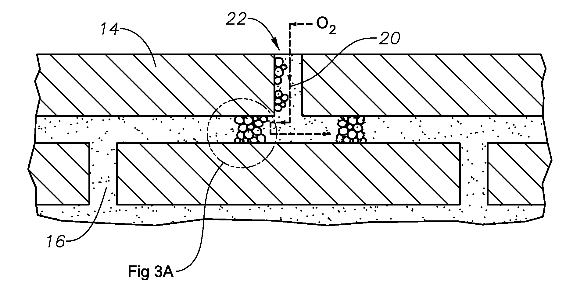
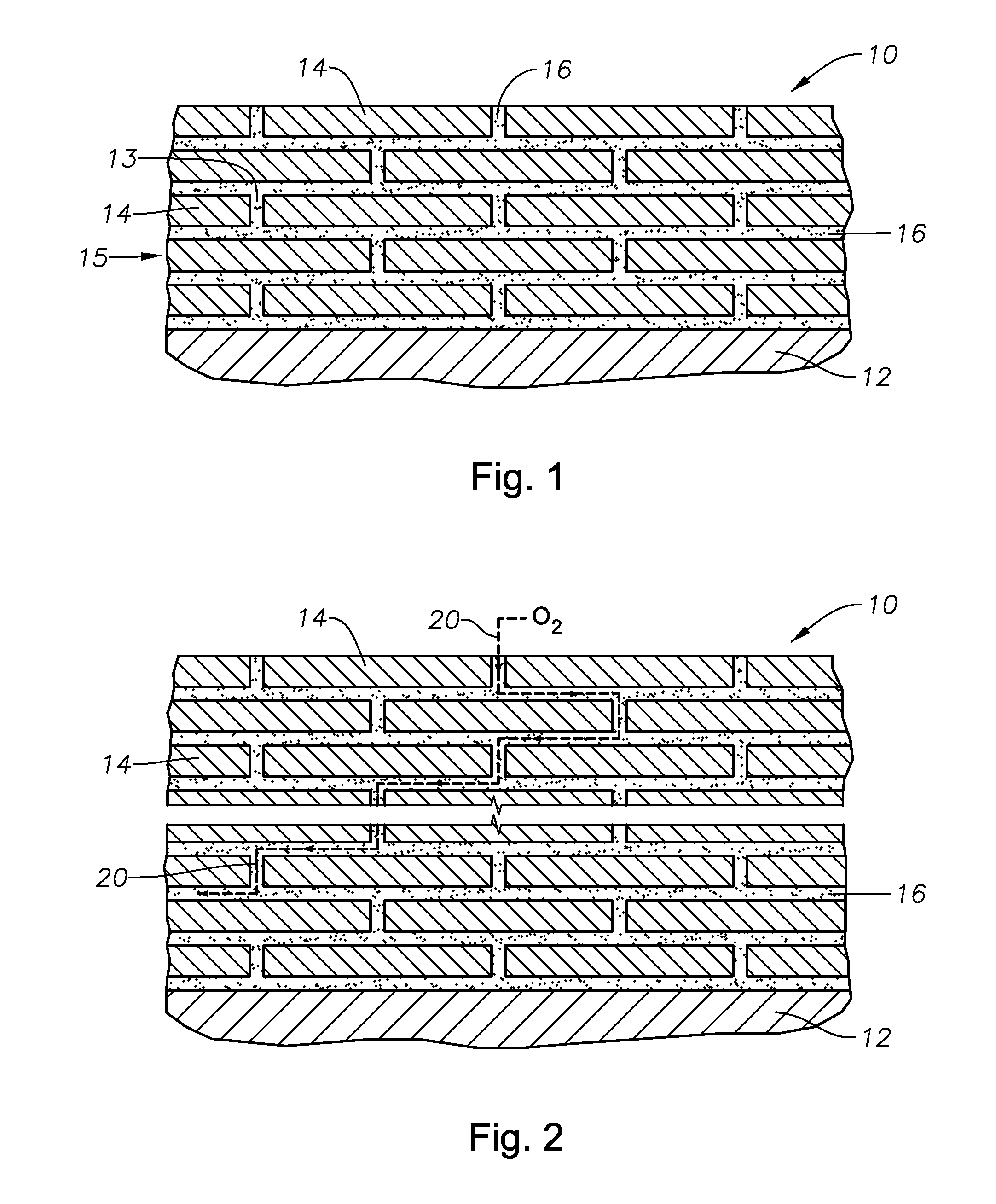
[0019]The EPC of the present invention may also be manufactured, for example, by preparing a skeleton or scaffold from carbon or other fugitive material covered with a refractory material. A binder or mortar can be prepared by converting the refractory material on the fugitive scaffold to an oxide for stable structure and improved sealing. With exposure to heat and / or oxygen, internal volume in the binder can be established by volatizing the fugitive component to allow for strain release. Further, the binder can be processed into a particulate size controlled, smooth paste capable of locating a plurality of platelets at a desired spacing from each other and arranging the platelets into a lamellar structure resembling a brick wall, when viewed in cross-section.
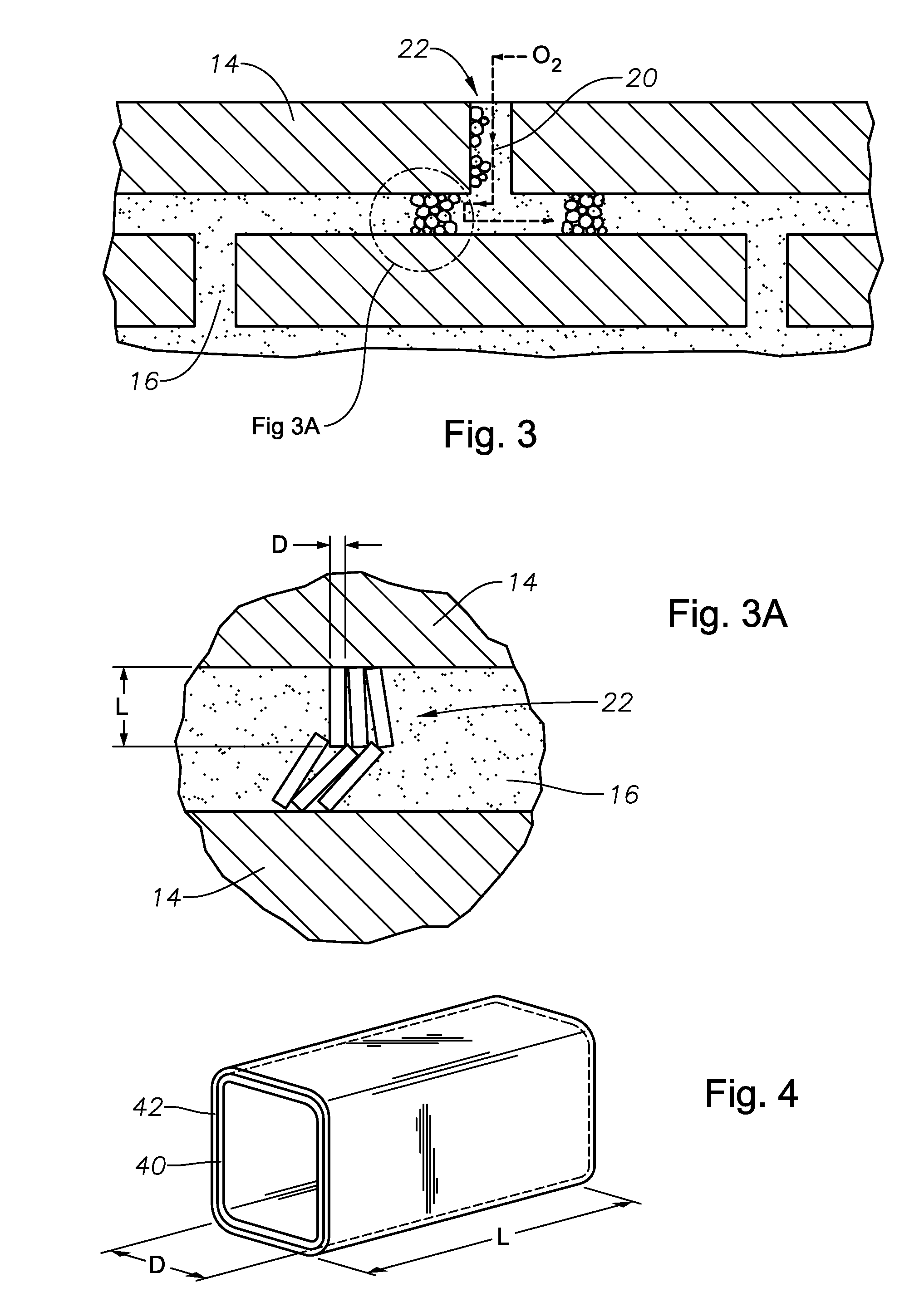
[0020]The complete invention consists of an engineered nacreous microstructure providing enhanced arrangement of platelets and high strain binder. Platelets may be physically organized to provide the enhanced arrangement. Chemical modification of the platelets may also be utilized to aid in organization. Locating the edge of one platelet with the center of the adjacent platelets is preferred to maximize the tortuous path through the coating and the strength of the coating. Chemical treatment to create charges or attractive forces of the platelet edges to the center may be used with flat platelets or in addition to shaping to further decrease the tendency of platelets edges to line up through the thickness, creating weak spots in the coating. The platelets consist of low porosity, low permeability refractory material resistant to degradation by oxygen and nitrogen with sufficient length over thickness to produce a tortuous diffusion path; typically with an L / D greater than 5, preferably greater than 10. The strain isolation of the typically high modulus platelets is provided by the weakly bonded and / or very compliant nature of binder constituents held in place with highly viscous glasses which provide cohesion to the coating, further stress relief and persistent sealing of the tortuous diffusion path. The strain isolation capability of the nacreous coating is derived from controlled introduction of free volume. Size reduction, orientation via processing and material formulation of the binder constituents organized into fine, irregular cells with fugitive fractions and low inter-laminar strength create the free volume. Heating and oxidizing remove the fugitive components and break weak cleavage bonds of the particulates creating the initial free volume to absorb thermal expansion and allow oxide sealant formation. This combination of materials can be fabricated as a paste or film adhesive.

Problems solved by technology

Current EPC's with silica based sealents are deficient at these temperatures because they rapidly degrade due to volatilization and active oxidation.
Higher temperature refractory based coatings are brittle and have poor CTE matches to 3000+F substrates leading to sealant failures.

Method used


Image

  • Ultra high temperature environmental protection coating
  • Ultra high temperature environmental protection coating
  • Ultra high temperature environmental protection coating

Examples


Embodiment Construction

[0030]The apparatus and method of the present disclosure will now be described more fully hereinafter with reference to the accompanying drawings in which embodiments are shown. This subject of the present disclosure may, however, be embodied in many different forms and should not be construed as limited to the illustrated embodiments set forth herein; rather, these embodiments are provided so that this disclosure will be thorough and complete, and will fully convey the scope of the invention to those skilled in the art. Like numbers refer to like elements throughout. For the convenience in referring to the accompanying figures, directional terms are used for reference and illustration only. For example, the directional terms such as “upper”, “lower”, “above”, “below”, and the like are used to illustrate a relational location.

[0031]It is to be understood that the subject of the present disclosure is not limited to the exact details of construction, operation, exact materials, or emb...


PUM

PropertyMeasurementUnit
Fractionaaaaaaaaaa
Fractionaaaaaaaaaa
Thicknessaaaaaaaaaa

Abstract

An environmental protective coating (EPC) for protecting a surface subjected to high temperature environments of more than 3000 degree F. The coating includes a dense platelet lamellar microstructure with a self-sealing, compliant binder material for holding the platelets together. The platelets may be formed from materials that are resistant to high temperatures and impermeable, such as ceramics. The lamellar microstructure creates a tortuous path for oxygen to reach the surface. The binder material may have free internal volume to increase the strain capability between the platelets and absorb increased volume during operation. The binder may be formed from a material that is softer and has a lower temperature capability than the platelets to provide the system with the required compliance and sealing capability. The binder may have sufficient glass content and glass-forming content for initial and long-term sealing purposes.

Description

TECHNICAL FIELD OF THE INVENTION[0001]The present invention relates generally to surface coatings and more particularly, an improved environmental barrier coating to protect a surface subjected to ultra high temperatures and oxidation.BACKGROUND OF THE INVENTION[0002]It is often necessary to protect high temperature articles with an Environmental Protection Coating (EPC). EPC's have insulative and chemical protection capabilities to protect surfaces from the harsh environment.[0003]EPC's are typically applied to hot sections of gas turbines or jet engines, such as combustor cans, nozzle guide vanes, and turbine blades. One of the functions of these coatings is to increase engine efficiency by elevating the operational temperature or reducing the need for cooling air. The use of thermal barrier coatings in large turbines for land-based power generation is critically necessary for an acceptable operating lifetime. EPC's and cooling mechanisms are often used in turbine systems to prote...

Claims


Application Information

Patent Timeline
IPC IPC(8): B32B3/14B05D3/02
CPCF01D5/288Y02T50/67F05D2300/512B64C3/36B64C11/205F05D2300/6033Y02T50/60
Inventor HECHT, DANIEL H.
Owner LOCKHEED MARTIN CORP
Learn More