Array of micromolded structures for sorting adherent cells

a micro-molded structure and adherent cell technology, applied in the field of adherent cell arrays, can solve the problems of affecting the morphology of cells, and affecting the viability of living cells, so as to achieve the effect of reducing the number of living cells

Active Publication Date: 2013-03-14
THE UNIV OF NORTH CAROLINA AT CHAPEL HILL
View PDF8 Cites 37 Cited by
  • Summary
  • Abstract
  • Description
  • Claims
  • Application Information

AI Technical Summary

Problems solved by technology

Unfortunately, enzymatic or mechanical release imposes significant drawbacks including loss of cell morphology, removal of cell surface markers, damage to cell membranes, alterations in cellular physiology and loss of viability.7-14
New techniques for adherent, mammalian cell selection address some of the challenges but remain limited for living cells.
Laser capture microdissection (LCM) (Arcturus; Mountain View, Calif.) has enabled single cells or small groups of selected cells to be obtained from tissue sections for genetic and proteomic studies, although most applications utilize fixed or frozen specimens.15 Protocols for use with live cells have been published, but are very low throughput and not suitable for isolating large numbers of single, living cells.16 Most applications of LCM utilize fixed or frozen specimens.15-18 Thus, these techniques have only partially met the needs of investigators for the positive selection of adherent, mammalian cells.
The system requires cells that grow in loosely adherent clusters or suspension-adapted versions of adherent cells growing in a semi-solid methylcellulose media, thus it is not applicable to the vast majority of mammalian cells.
The most serious limitation is that an expensive optical system is required to release a target pallet from the array.
However, a very low energy of release requires precise control of the adhesion force between the pallet and glass to keep pallets attached to the array until released is desired.
In addition to the limitations required for laser-based release, the pallet array itself has drawbacks.
First, the pallet array is made from photoresist having autofluorescence in the range of 480-520 nm, which coincides with the range of wavelengths of the most frequently used dyes (e.g. FITC, Oregon green, Alexa Fluor 488, etc) for fluorescence imaging.22, 24 Second, the fabrication of the pallet array is expensive and complicated, since the whole fabrication process needs a clean environment and expensive microfabrication tools including mask aligner, photoresist spin coater, metal evaporator, and plasma cleaner.19

Method used


Image

  • Array of micromolded structures for sorting adherent cells
  • Array of micromolded structures for sorting adherent cells
  • Array of micromolded structures for sorting adherent cells

Examples


example 1

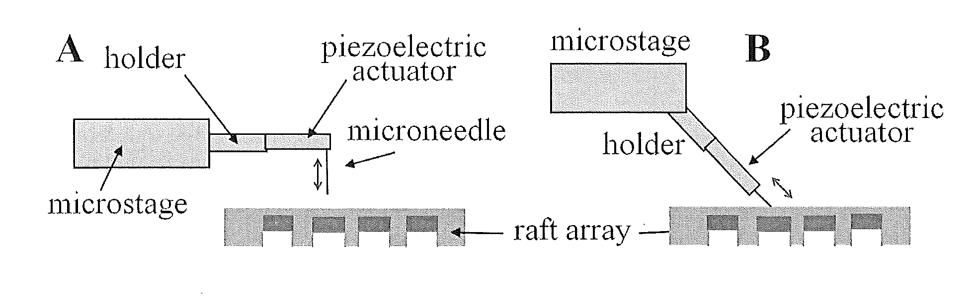
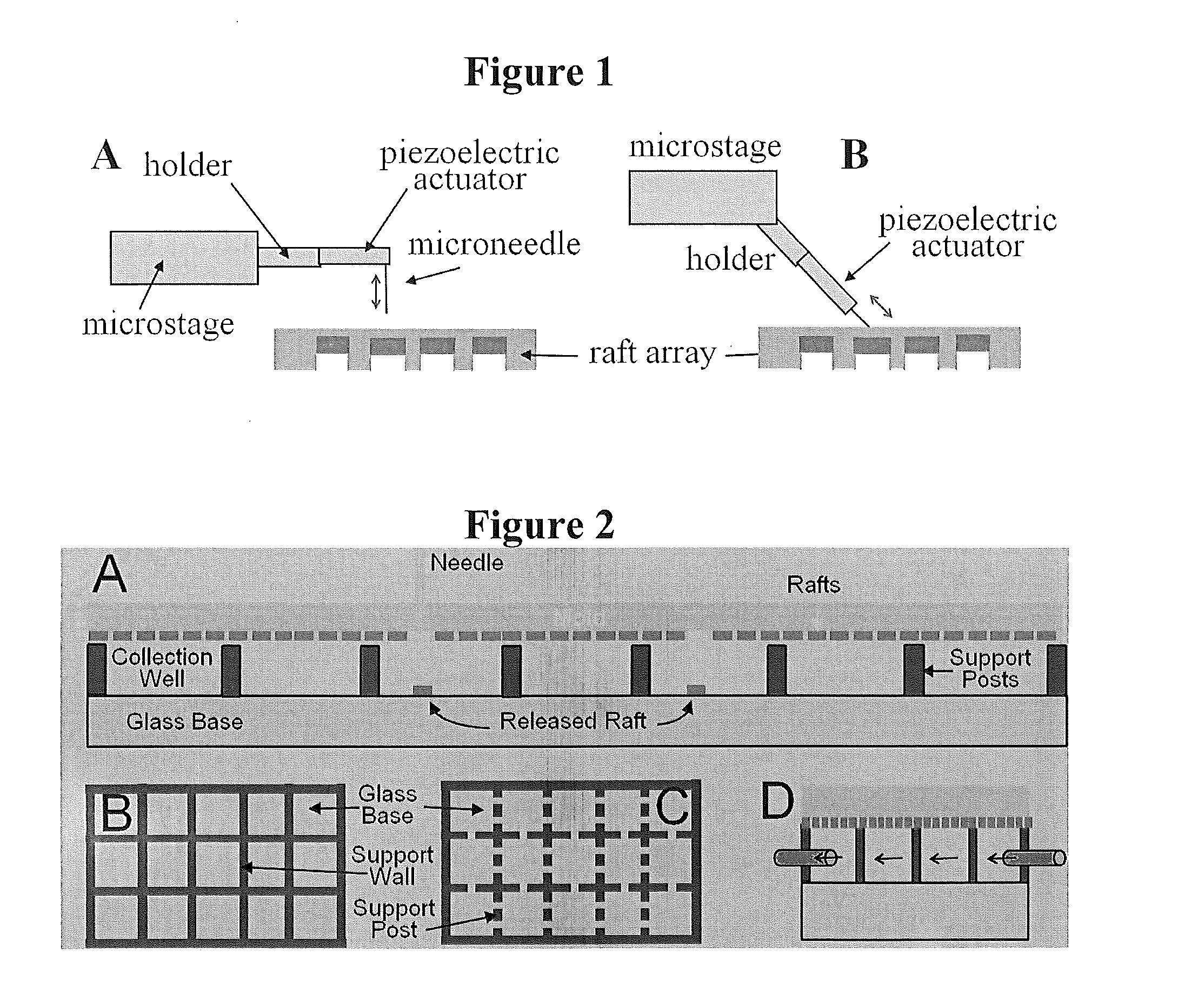
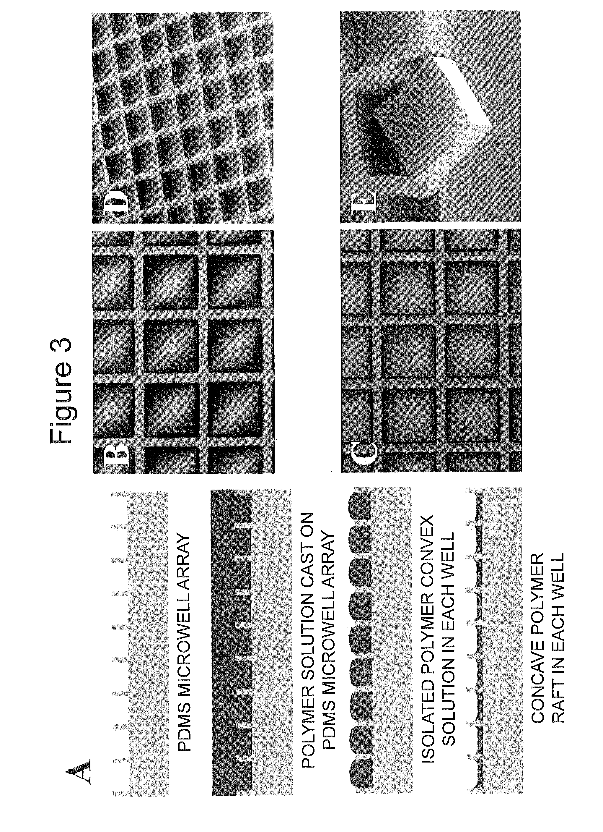
[0072]As one non-limiting example of the invention, we describe here an improved technology for creating an array of individually releasable elements which overcomes the above limitations. Instead of fabricating pallets on glass using photolithography and photoresist, we use an array of microwells made from PDMS as the template to micromold the rafts. The micromolded raft contains no photoinitiator and therefore has a low autofluorescence background. The micromolding process does not require any microfabrication tool, so the fabrication becomes extremely simple and inexpensive. Since the raft is located inside the microwell, cells can fall into the microwell and then attach, thus eliminating the necessity of using a virtual air wall or PEG hydrogel wall to localize cell attachment. The most important improvement is to replace the expensive optical system with a low-cost needle release system. A selected raft can be effectively released from the array by the action of a needle insert...

example 2

Coating Microraft Arrays with Biologically Active Molecules

[0113]1. Coating with Extracellular Matrices to Enhance Cell Attachment.

[0114]Extracellular matrices (ECMs), such as collagen, gelatin, laminin and fibronectin, can be coated on the microraft surface to enhance cell attachment. As the first example, a microraft array was coated with 100 μg / mL collagen (type I from rat tail) for 1 h. HeLa cells attached quickly to the microrafts in 2 h (FIG. 10B). As a control, cells didn't attach to the non-coated array at the 2 h time point (FIG. 10A), although they did adhere and spread after 6 h.

[0115]As a second example, in-vitro culture of stem cells generally requires supplying with ECMs to mimic in-vivo environment for self renewal. Matrigel can be coated on the microraft array for culturing stem cells. FIG. 11 shows mouse embryonic stem cell line ES129 cultured on the array at 50 h in the presence of leukemia inhibitory factor (LIF). The array was coated with Matrigel prior to platin...

example 3

Polystyrene and Other Carrier Materials

[0136]An elastomeric PDMS mold (75 mm×50 mm×0.5 mm) was fabricated by casting PDMS on an SU-8 master fabricated by standard photolithography on a glass slide. The SU-8 thickness was 10-250 μm. Approximately 4 g of polystyrene solution (25 wt % in GBL) was added to the PDMS mold (not shown). This amount of solution generates a film of approximately 0.25 mm thickness after baking. Polystyrene solution was found to be dewetting on PDMS surface during baking, causing the solution to shrink. To prevent the dewetting, the PDMS mold was treated with air plasma for 1 min prior to the addition of the polystyrene solution. This treatment did not affect the mold release in the final step. A short (1 min) degas by oil pump was required to remove the trapped air bubbles in the PDMS mold. Since GBL has a high boiling point of 204° C., polystyrene solution did not evaporate or boil during degassing. The polystyrene solution remained as a clear, viscous soluti...


PUM

PropertyMeasurementUnit
widthaaaaaaaaaa
heightaaaaaaaaaa
thicknessaaaaaaaaaa

Abstract

An apparatus for collecting or culturing cells or cell colonies includes: a common substrate formed from a flexible resilient polymeric material and having a plurality of wells formed therein; and a plurality of rigid cell carriers releasably connected to said common substrate, with said carriers arranged in the form of an array, and with each of the carriers resiliently received in one of the wells. A method of collecting or culturing cells or cell colonies with such an apparatus is carried out by depositing a liquid media carrying cells on the apparatus so that said cells settle on or adhere to said the carriers; and then (c) releasing at least one selected carrier having said cells thereon by gradual application of release energy to each carrier from the cavity in which it is received (e.g., by pushing with a probe).

Description

RELATED APPLICATIONS[0001]This application is a continuation-in-part of PCT Application No. PCT / US2011 / 025018, filed Feb. 16, 2011, which in turn claims the benefit of U.S. Provisional Applications No. 61 / 375,596, filed Aug. 20, 2010, and 61 / 305,067, filed Feb. 16, 2010, the disclosures of all of which are incorporated by reference herein in their entirety.STATEMENT OF FEDERAL SUPPORT[0002]This invention was made with Government support under grant numbers EB007612, HG004843, and EB012549 from the National Institutes of Health. The US Government has certain rights to this invention.BACKGROUND OF THE INVENTION[0003]The selection and isolation of single cells from a mixed population is a common procedure performed throughout biomedical research. For example, during the development of cell lines that are genetically engineered, derived from stem cells, or grown from patient cell lines, single cells must be isolated and then cloned to form a homogeneous population. A variety of strategi...

Claims


Application Information

Patent Timeline
Patent Type & Authority Applications(United States)
IPC IPC(8): C40B50/06C40B60/14
CPCC12M25/16C12M23/12C12M47/02C12M47/04C12M25/04B01J19/0046B01J2219/00452B01J2219/00743C12M23/20C12M23/22C12N2509/10C12N1/02C12N5/0068
Inventor ALLBRITTON, NANCYSIMS, CHRISTOPHERWANG, YULISHAH, PAVAK KIRIT
Owner THE UNIV OF NORTH CAROLINA AT CHAPEL HILL
Why Eureka
Try Eureka