Selective placement of carbon nanotubes via coulombic attraction of oppositely charged carbon nanotubes and self-assembled monolayers

a carbon nanotube and self-assembled technology, applied in the field of placing carbon nanotubes, can solve the problems of inability to reach recessed hydrophilic areas having small widths, undesirable bundled or multi-layered cnts, poor selectivity, etc., to achieve the effect of reducing the formation of multi-layer cnts or bundled cnts, reducing the formation of bundled cnts, and increasing the density of nanotubes

Active Publication Date: 2013-04-04
IBM CORP
View PDF8 Cites 34 Cited by
  • Summary
  • Abstract
  • Description
  • Claims
  • Application Information

AI Technical Summary

Benefits of technology

[0012]Advantages of the present invention include increased density of nanotubes, and reduced formation

Problems solved by technology

Bundled or multilayered CNTs are undesirable because a transistor made from them requires higher voltage to turn on an off.
The described method has another drawback in that a solution of CNTs is not able to reach recessed hydrophilic areas

Method used


Image

  • Selective placement of carbon nanotubes via coulombic attraction of oppositely charged carbon nanotubes and self-assembled monolayers
  • Selective placement of carbon nanotubes via coulombic attraction of oppositely charged carbon nanotubes and self-assembled monolayers
  • Selective placement of carbon nanotubes via coulombic attraction of oppositely charged carbon nanotubes and self-assembled monolayers

Examples


example i

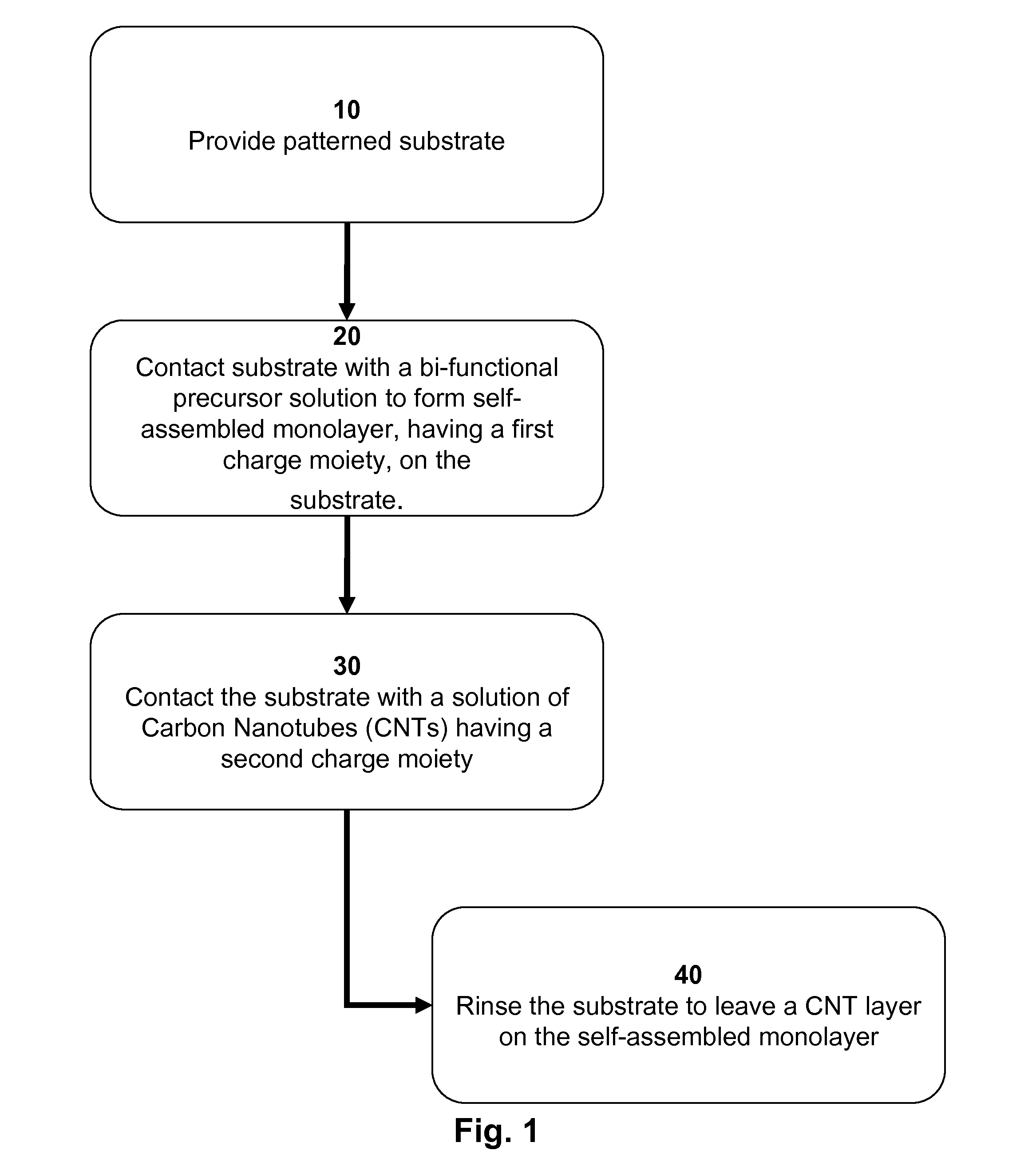
[0057]Positively charged bi-functional precursor molecules for self-assembly. Potassium cyanide (50 mg) was added to a solution of methyl isonicotinate (1.17 g, 0.01 mole) and 50% hydroxylamine in water (1.3 g, 0.02 mole) in 10 mL tetrahydrofuran and 5 mL methanol. After stirring the mixture at room temperature for 18 hours, the precipitate was filtered and washed with diethyl ether and dried to give analytically pure N-hydroxy isonicotinamide. The latter was added to 5% methyl iodide in methanol and stirred at room temperature for two days. Methanol was evaporated under reduced pressure and the solid residue was crystallized from ethanol resulting in pure 4-hydroxamido-N-methylpyridinium iodide.

example ii

[0058]Preparation of negatively-charged CNTs by functionalization. Nitrosonium tetrafluoroborate (12 mg, 1 mmole) was added to a suspension of methyl 4-aminobenzoate (15 mg, 1 mmole) in 5 mL of acetonitrile. The resulting solution was added drop-wise to an aqueous suspension of single-walled carbon nanotubes (1 mg) in water containing 1% sodium dodecylsulfate. After standing for 18 hours, the solution was centrifuged and the sediments were added to 10 mL of 10% methanolic potassium hydroxide solution. After stirring for 4 hours, 20 mL of acetone was added and the mixture centrifuged. The supernatant liquid was discarded and the sediment was dissolved in de-ionized water resulting in an aqueous solution of negatively charged carbon nanotubes.

example iii

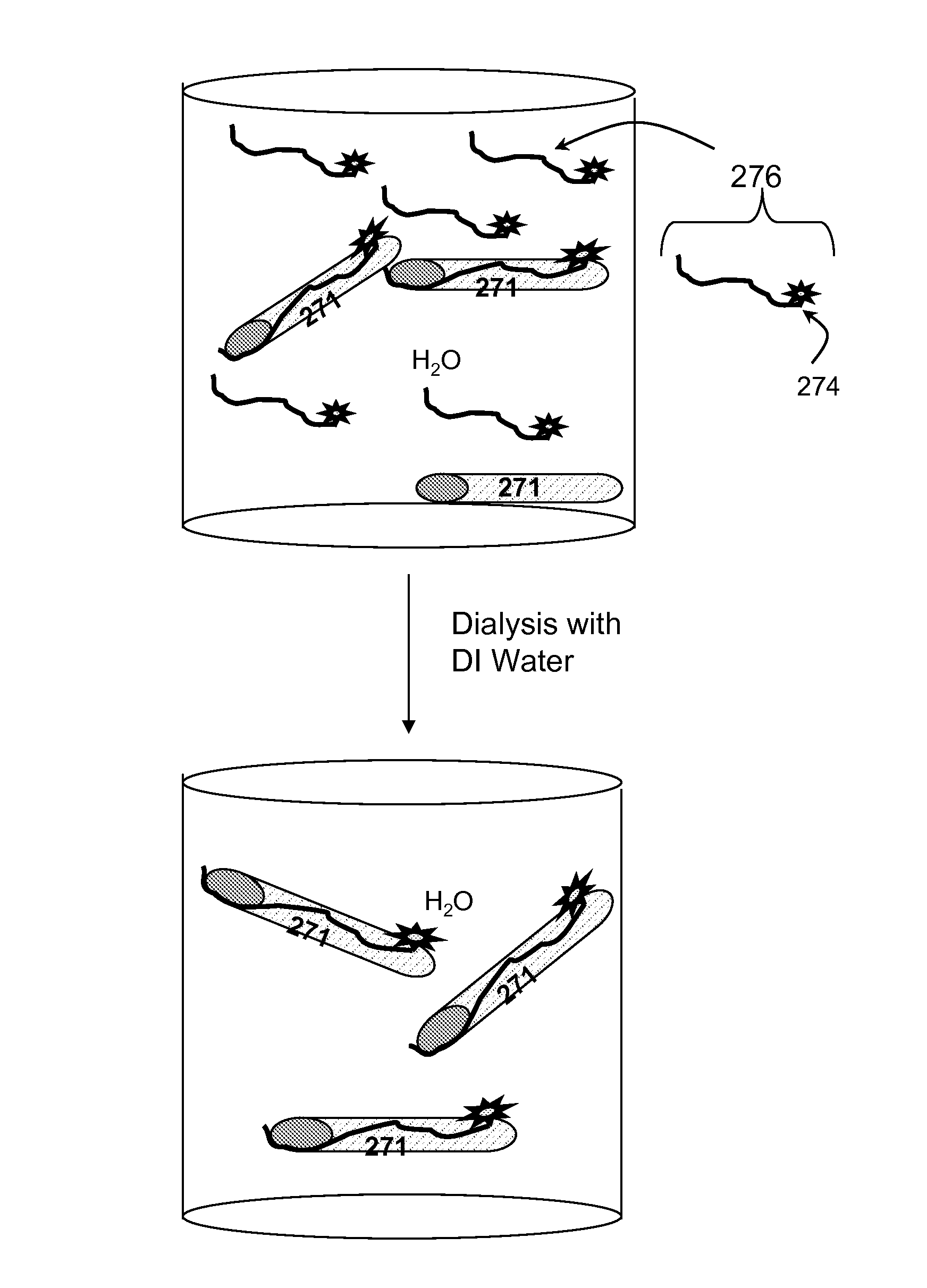
[0059]Preparation of an aqueous dispersion of CNTs coating in with a monolayer of anionic surfactant. Dispersion of carbon nanotubes in 1% sodium dodecylsulfate was dialyzed with pure water for several days, during which fresh water was used after 24 hours. After several times dialyzing with fresh water, the solution inside the filter contains no free surfactant and all surfactants are attached to carbon nanotubes.


PUM


Abstract

A method of forming a structure having selectively placed carbon nanotubes, a method of making charged carbon nanotubes, a bi-functional precursor, and a structure having a high density carbon nanotube layer with minimal bundling. Carbon nanotubes are selectively placed on a substrate having two regions. The first region has an isoelectric point exceeding the second region's isoelectric point. The substrate is immersed in a solution of a bi-functional precursor having anchoring and charged ends. The anchoring end bonds to the first region to form a self-assembled monolayer having a charged end. The substrate with charged monolayer is immersed in a solution of carbon nanotubes having an opposite charge to form a carbon nanotube layer on the self-assembled monolayer. The charged carbon nanotubes are made by functionalization or coating with an ionic surfactant.

Description

BACKGROUND OF THE INVENTION[0001]1. Field of the Invention[0002]The present invention generally relates to a method of placing carbon nanotubes (herein after “CNTs”) on a substrate. In particular, the invention relates to selective placement of charged CNTs on a pre-patterned surface having an oppositely charged, self-assembled monolayer.[0003]2. Description of Related Art[0004]CNTs can be semiconducting and therefore are of interest as channel materials for Field Effect Transistors (herein after “FET”). Accordingly, methods of placing CNTs on a substrate for use in FETs are being explored.[0005]One approach to placing CNTs on a substrate involves directed assembly of CNTs from a suspension. In this approach, a substrate is patterned to define areas to which the CNT will have an affinity. The affinity is due to functionalization of either the substrate or the CNT to promote bonding between the substrate and the CNT.[0006]In one instance, to place CNTs on a substrate, the prior art s...

Claims


Application Information

Patent Timeline
IPC IPC(8): H01L29/06H01L21/20C07D213/76B82Y40/00B82Y99/00
CPCB82Y40/00C07D213/76H01L51/0003B82Y10/00H01L51/0558H01L29/0676H01L51/0049C07D213/79H10K71/12H10K85/225H10K10/484C01B32/158C01B32/16H01L29/0669C01B2202/08H10K85/221
Inventor AFZALI-ARDAKANI, ALIPARK, HONGSIKTULEVSKI, GEORGE STOJAN
Owner IBM CORP
Why Eureka
Try Eureka