Electronic component module and method of manufacturing the same

a technology of electronic components and components, applied in the field of electronic component modules, can solve the problems of reducing the size of the substrate and/or electronic components, affecting the reliability of affecting the reliability of electrical connection, so as to improve the mechanical strength and electrical connection reliability, the effect of improving the electromagnetic noise shielding performance and the shielding properties

Inactive Publication Date: 2013-10-03
TDK CORPARATION
View PDF5 Cites 29 Cited by
  • Summary
  • Abstract
  • Description
  • Claims
  • Application Information

AI Technical Summary

Benefits of technology

[0030]In the electronic component module according to the present invention, the conductive shield, provided so as to further cover the molding resin which covers the surface of the substrate and the electronic components and so as to be connected to the ground wires exposed on the lateral surfaces of the substrate, includes the first filler and the second filler, the average particle diameter of the first filler being ½ or less of the thickness of the ground wires, the second filler forming a metallic bond in the temperature range of 250 degrees Celsius or lower. Thus, the electronic component module according to the present invention can significantly improve the electromagnetic noise shielding performance (shielding properties) and the mechanical strength and electrical connection reliability of the conductive shield (electromagnetic shield) itself and between the conductive shield and the ground wires as compared to the related art.
[0031]In addition, in using the first filler consisting of Cu or mainly containing Cu and the second filler consisting of a metal which is easier to become corroded than Ag or mainly containing the metal which is easier to become corroded than Ag, by heating and curing the conductive paste, which contains such filers and which is applied onto the molding resin, in the ambient air with a reduced oxygen concentration relative to the oxygen concentration under the atmospheric pressure, the first filler, second filler and ground wires can be properly joined by the respective metallic bonds, which allows for the suppression of an excessive increase in the conduction resistance (volume resistance value) and a reduction in the amount of reducing agent to be added to the conductive paste, etc. for forming the conductive shield to thereby achieve improvements in the corrosion resistance of Cu and in the storage stability of the conductive paste.

Problems solved by technology

While such needs exist, the above-mentioned electronic component module having a metallic casing as electromagnetic shielding cannot secure a sufficient height for the side walls of the substrate and thus the metallic casing cannot be joined with the substrate at the side walls thereof, and such electronic component module then has to have a structure in which a plate-shaped metallic casing is mounted on the module having a land on a substrate surface and in which the land and the metallic casing are joined with each other using solder or the like.
This structure leaves the land portion as a dead space and cannot allow any electronic component to be mounted thereon or any wiring layer to be provided therein and thus such structure is not preferable in terms of size reduction and high-density packaging.
In addition, since the electronic component module having the electromagnetic shielding layer formed by metal plating on the molding resin uses, in many cases, various types of chemical solutions for plating, the substrate and / or electronic components may be damaged.
Furthermore, the plating process requires a relatively long time and the scale of the device becomes relatively large, the productivity will disadvantageously be lowered.
In addition, a molding resin typically used in transfer molding sometimes contains about 90 mass % of filler (e.g., molten silica) and the adhesion strength (bonding strength) between the filler in the molding resin and the metal plate is small, which may cause problems such as delamination of the metal plate and a decrease in yield.
However, the inventors of the present invention, after having devoted themselves to study of the electromagnetic noise shielding performance of the electromagnetic shielding layer and the connection reliability between the electromagnetic shielding layer and the ground pattern on the substrate, etc. of the related-art electronic component module described in Patent Document 1, found that the electromagnetic noise shielding performance and the connection reliability were still insufficient.
However, the configuration of the related art electromagnetic shielding layer makes it difficult to securely connect the ground pattern exposed on the lateral surfaces of the substrate and the electromagnetic shielding layer and thus the above requirement for the electronic component module cannot be sufficiently satisfied.
When the first filler and second filer formed from specific materials are used in terms of conductivity, economic efficiency and melting properties at a low temperature, some materials may cause, due to the corrosion (oxidation) thereof, disadvantages in which proper joining cannot be formed by the metallic bond or a conduction resistance (volume resistance value) is excessively increased.
Although the addition of a reducing agent (antioxidant) to the conductive paste, etc. for forming the conductive shield is effective in order to prevent such disadvantages, the addition of an excess amount of such reducing agent may cause another problem in which a metal other than the filler, being the target of preventing the generation of an oxide film and removing an oxide film, may become corroded more easily or the storage stability of the conductive paste may be deteriorated.

Method used


Image

  • Electronic component module and method of manufacturing the same
  • Electronic component module and method of manufacturing the same
  • Electronic component module and method of manufacturing the same

Examples


example 1

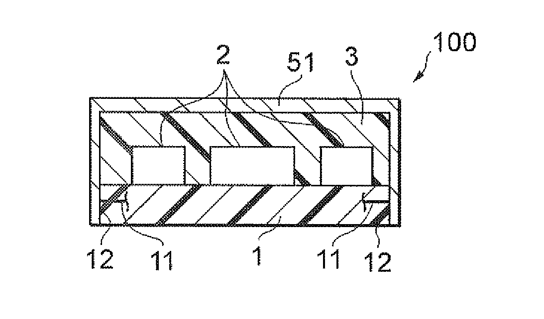
[0069]A conductive paste was prepared using flat-shaped Ag powder having an average particle diameter of 5 μm as the first filler (base filler), Ag nanofiller having an average particle diameter of 30 nm as the second filler, an epoxy resin (liquefied bisphenol A epoxy resin and imidazole) and butyl carbitol acetate. The total content of the first filler and second filler in this conductive paste was 90 mass % on the basis of the mass of the epoxy resin. The conductive paste was provided by stencil printing on the substrate 1 and molding resin 3, then heated and cured at 70 degrees Celsius for 30 minutes and at 160 degrees Celsius for 60 minutes to form a cured film of the conductive shield 51, to thereby prepare an electronic component module according to the present invention having the same configuration as the electronic component module 100 shown in FIG. 3.

example 2

[0070]An electronic component module according to the present invention was prepared in the same manner as in Example 1, except that Cu-coated Ag powder having an average particle diameter of 5 μm was used as the first filler and Sn—Bi spherical powder having an average particle diameter of 5 μm was used as the second filler. The total content of the first filler and second filler in this conductive paste was 90 mass % on the basis of the mass of the epoxy resin.

[0071]Test and Evaluation 1: Observation on Cross Sections of Conductive Shields (States of Neck Growth)

[0072]FIG. 4 and FIGS. 5A and 5B are electron micrographs showing, in enlarged views, the cross sections of conductive shields in the electronic component modules obtained in Comparative Example 1 and Examples 1 and 2, respectively. Note that one tick of the scale shown in the photos in FIG. 4 and FIGS. 5A and 5B corresponds to 20 μm. The result shown in FIG. 4 indicates that individual particles in the metal filler (indiv...

example 7

[0086]An electronic component module according to the preset invention was prepared in the same way as Example 1 except that: Cu-coated Ag flat-shaped powder having an average particle diameter of 5 μm was used as the first filler; Sn—Bi spherical powder having an average particle diameter of 5 μm was used as the second filler, butyl carbitol acetate and carboxylic acid were used; the conducive paste was heated under the conditions of 150 degrees Celsius for 20 minutes and 180 degrees Celsius for 60 minutes; and the oxygen concentration of the ambient air during the heating and curing process of the conductive paste was controlled to 500 ppm or less.

[0087]Test and Evaluation 4: Observation on Cross Section of Conductive Shield (State of Neck Growth)

[0088]The cross sections of the conductive shields in the electronic component modules obtained in Comparative Example 4 and Example 7 were observed in enlarged views using an electron microscope in the same way as in Test and Evaluation ...


PUM


Abstract

An electromagnetic component module includes: a molding resin provided so as to cover electronic components mounted on a substrate and a surface of the substrate; and a conductive shield formed so as to further cover the molding resin. The conductive shield includes a first filler and a second filler which are different from each other and the conductive shield is connected to ground wires exposed on lateral surfaces of the substrate. The average particle diameter of the first filler is ½ or less of the thickness of the ground wires and the second filler forms a metallic bond in the temperature range of 250 degrees Celsius or lower.

Description

CROSS-REFERENCES TO RELATED APPLICATIONS[0001]This application relates to and claims priority from Japanese Patent Application No. 2012-077034, filed on Mar. 29, 2012, the entire disclosure of which is incorporated herein by reference.BACKGROUND[0002]1. Field of the Invention[0003]The invention relates to an electronic component module and method of manufacturing the same.[0004]2. Description of Related Art[0005]An electronic component module has electronic components used for electronic equipment, including active components such as semiconductor devices (e.g., IC chips), and passive components such as capacitors, inductors (coils), thermistors and resistors, in such a manner that they are mounted on a single substrate. Of such electronic component modules, an electronic component module covered with a metallic casing or housed in a metallic casing and an electronic component module in which electronic components are covered with a molding resin and then an electromagnetic shieldin...

Claims


Application Information

Patent Timeline
Patent Type & Authority Applications(United States)
IPC IPC(8): H01L23/60
CPCH01L23/60H01L2924/19105H01L24/97H01L23/552H01L2924/01322H01L2924/15787H01L2924/181H01L2924/12042H01L23/3135H01L2924/00H01L2924/00012
Inventor KAWABATA, KENICHIKOMATSU, SEIKO
Owner TDK CORPARATION
Why Eureka
Try Eureka