Lithium ion battery graphite negative electrode material and preparation method thereof

a technology of graphite and lithium ion batteries, which is applied in the direction of cell components, coatings, chemistry apparatuses and processes, etc., can solve the problems of poor compatibility between natural graphite and electrolytes, graphite layer peeling, and great disadvantage in the cycle stability of batteries, and achieve excellent cycle stability and high rate performance.

Active Publication Date: 2014-10-09
BTR NEW MATERIAL GRP CO LTD
View PDF2 Cites 22 Cited by
  • Summary
  • Abstract
  • Description
  • Claims
  • Application Information

AI Technical Summary

Benefits of technology

[0004]Regarding the deficiency of the prior art, one object of the present invention lies in providing a lithium ion battery graphite negative electrode material, which possesses the features of high rate performance and excellent cycle stability at high and low-temperature.

Problems solved by technology

The compatibility between natural graphite and electrolytes is poor, and co-intercalation of solvated lithium ions is likely to occur as charging, which makes the graphite layer peel off.
Further, the electrolyte continues to react with the graphite layers, leading to a great disadvantage in cycle stability of the battery.
However there still exist many problems such as bad contact between one electrode material particle and another, and between one and a current collector, large surface resistance, poor peel strength, cycle swelling during charge-discharge process, etc.
These problems above seriously affect the cycle life and stability of a lithium ion battery.
However, the specific surface area of the material obtained by this method is larger and the surface-coating layer formed merely by the vapor deposition method is looser, which leads to a poor stability of the SEI membrane formed during charge-discharge process, more consummation of electrolyte, and thus there still exists in deficiency in cycle stability of batteries at high temperature.

Method used

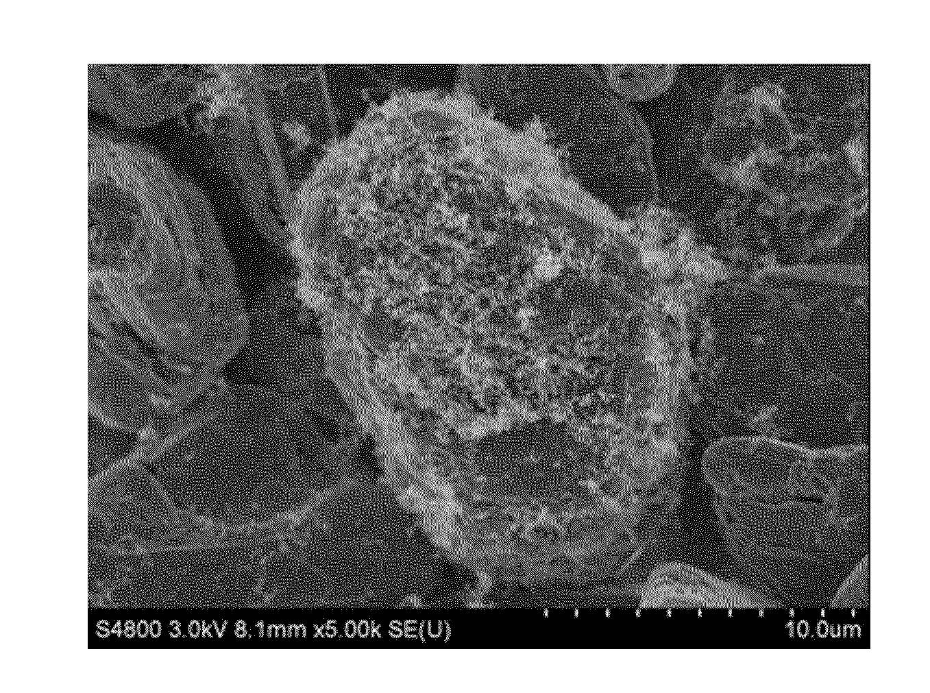
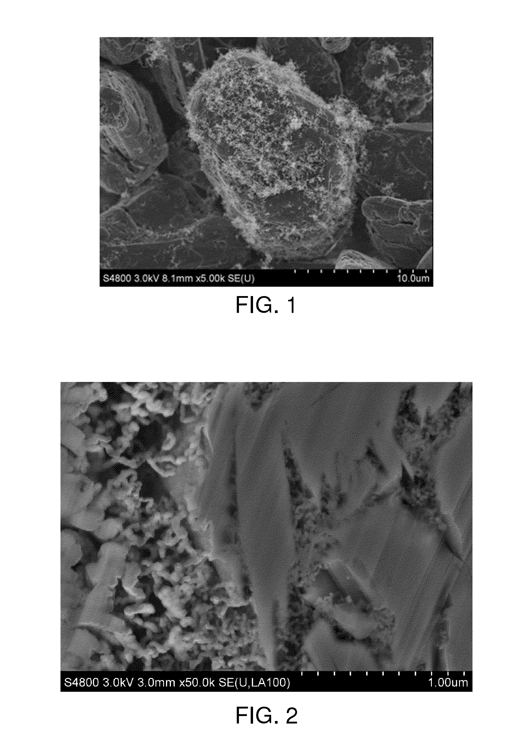

Image

  • Lithium ion battery graphite negative electrode material and preparation method thereof
  • Lithium ion battery graphite negative electrode material and preparation method thereof
  • Lithium ion battery graphite negative electrode material and preparation method thereof

Examples


example 1

[0072]Natural spherical graphite having a carbon content of more than 85% and a particle size of 3˜40 μm was placed in a VC-500 type mixer. Coal tar pitch was introduced in the mass ratio of 0.5:100 to the natural spherical graphite, to conduct solid-phase mixing with rotational speed of 5000 rpm and mixing time of 5 min, obtaining a mix. The mix was placed in a crucible equipped in a tunnel kiln. The volume of the mix was 50% of the capacity of the crucible. Nitrogen gas was aerated in a flow rate of 10 m3 / h, the temperature was elevated up to 300° C. in a heating rate of 0.1° C. / min, and the heat treatment was conducted for 1 h. The heat-treatment product was placed in a rotatory furnace with a rotational speed of 1 rpm. Nitrogen gas was aerated in a flow rate of 0.05 L / min, the temperature was elevated up to 300° C. in a heating rate of 0.1° C. / min, and maintained for 0.5 h. Then the carbon source gas, that is, natural gas was aerated in a flow rate of 0.05 L / min to perform vapor...

example 2

[0073]Natural flake graphite having a carbon content of more than 85% and a particle size of 3˜40 μm was placed in a VC-500 type mixer. Petroleum asphalt was introduced in the mass ratio of 30:100 to the natural flake graphite, to conduct solid-phase mixing with a rotational speed of 500 rpm and mixing time of 180 min, obtaining a mix. The mix was placed in a crucible equipped in a tunnel kiln. The volume of the mix was 10% of the capacity of the crucible. Nitrogen gas was aerated in a flow rate of 10 m3 / h, the temperature was elevated up to 1300° C. in a heating rate of 20° C. / min, and the heat treatment was conducted for 30 h. The heat-treatment product was placed in a rotatory furnace with a rotational speed of 20 rpm. Nitrogen gas was aerated in a flow rate of 10 L / min, the temperature was elevated up to 1300° C. in heating rate of 50° C. / min, and maintained for 1 h. Then the carbon source gas methane was aerated in a flow rate of 10 L / min to perform vapor deposition for 0.1 h. ...

example 3

[0074]Artificial graphite having a carbon content of more than 85% and a particle size of 3˜40 μm was placed in a VC-150 type mixer. Coal tar pitch was introduced in the mass ratio of 10:100 to the natural flake graphite, to conduct solid-phase mixing with a rotational speed of 3000 rpm and mixing time of 150 min, obtaining a mix. The mix was placed in a crucible equipped in a tunnel kiln. The volume of the mixed material was 50% of the capacity of the crucible. Nitrogen gas was aerated in a flow rate of 5 m3 / h, the temperature was elevated up to 600° C. in a heating rate of 10° C. / min, and the heat treatment was conducted for 10 h. The heat-treatment product was placed in a rotatory furnace with a rotational speed of 10 rpm; nitrogen gas was aerated in a flow rate of 5 L / min. The temperature was elevated up to 900° C. in a heating rate of 25° C. / min, and maintained for 3 h. Then the carbon source gas, that is, acetylene was aerated in a flow rate of 5 L / min to perform vapor deposit...


PUM

PropertyMeasurementUnit
specific surface areaaaaaaaaaaa
diameteraaaaaaaaaa
lengthaaaaaaaaaa

Abstract

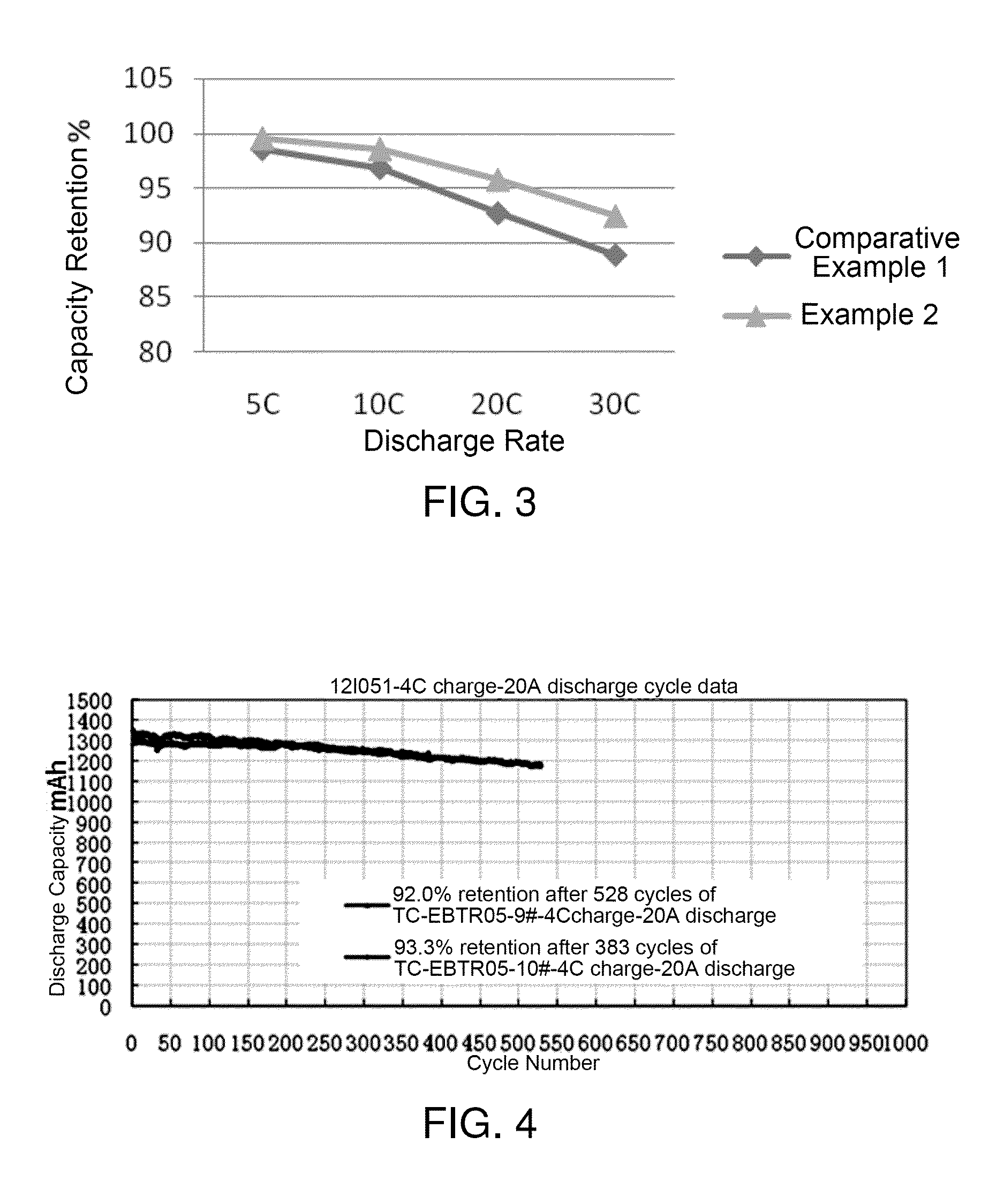
A lithium ion battery graphite negative electrode material and preparation method thereof. The lithium ion battery graphite negative electrode material is a composite material including graphite substrates, surface coating layers coated on the graphite substrates and carbon nanotubes and/or carbon nanofibers grown in situ on the surface of the surface coating layers. The preparation method thereof includes, in solid phase or liquid phase circumstance, the coated carbon material precursor forms the surface coating layer of amorphous carbon by carbonization, and then carbon nanotubes and/or carbon nanofibers having high conductive performance are formed on the surface of the surface coating layers by vapor deposition. This coating mode of the combination of solid phase with gas phase or of liquid phase and gas phase makes the amorphous carbon formed on the surface of the graphite substrates more uniform and dense. The lithium ion battery graphite negative electrode material has properties of high charging-discharging efficiency at first time and excellent cycle stability at either high or low temperatures. The charging-discharging efficiency at first time is up to more than 95%, and the capacity retention after 528 cycles is more than 92%.

Description

TECHNICAL FIELD[0001]The present invention relates to the field of lithium ion battery negative electrode materials, particularly to a lithium ion battery graphite negative electrode material and a preparation method thereof.BACKGROUND ART[0002]Commercial lithium ion battery carbon negative electrode materials primarily include natural graphite and artificial graphite. The compatibility between natural graphite and electrolytes is poor, and co-intercalation of solvated lithium ions is likely to occur as charging, which makes the graphite layer peel off. Further, the electrolyte continues to react with the graphite layers, leading to a great disadvantage in cycle stability of the battery. At present, techniques to modify the materials mainly include surface-coating to construct a core-shell structure by multiphase coating technology, doping and surface oxidation, etc., thereby improving electrochemical properties. However there still exist many problems such as bad contact between on...

Claims


Application Information

Patent Timeline
Patent Type & Authority Applications(United States)
IPC IPC(8): H01M4/36C01B31/04H01M4/587
CPCH01M4/366C01B31/04H01M4/587C01B32/05C01B32/162C01B2202/34C01B2202/36H01M10/052Y02E60/10Y02E60/50H01M4/1393H01M4/133H01M4/583H01M4/96
Inventor YUE, MINLIANG, YANYAN, HUIQINGDENG, MINGHUAHUANG, YOUYUAN
Owner BTR NEW MATERIAL GRP CO LTD
Why Eureka
Try Eureka