Polymer solar cell device and method for preparing same

a solar cell and polymer technology, applied in the field of solar cells, can solve the problems of affecting the energy conversion efficiency, the thickness of the buffer layer is needed, and the open circuit voltage and photoelectric conversion efficiency of solar cells is very low, so as to facilitate the injection of electrons, reduce the barrier of the electrons on the interface, and improve the electron transport rate

Inactive Publication Date: 2014-11-06
OCEANS KING LIGHTING SCI&TECH CO LTD +1
View PDF2 Cites 3 Cited by
  • Summary
  • Abstract
  • Description
  • Claims
  • Application Information

AI Technical Summary

Benefits of technology

[0006]Accordingly, it is necessary to provide a polymer solar cell device which is capable of improving the electron transport rate.
[0025]In the polymer solar cell device, the electron transporting layer is made of electron transporting material doped with cesium salt and metal particle. An n-doping is formed by doping cesium salt to the electron transporting material, which improves the electron transport rate effectively, and the energy band between the electron transporting layer and the active layer is bended, the injection barrier of the electrons on this interface is reduced; it is conducive to the injection of the electrons. Furthermore, the barrier between the electron transporting layer and the cathode is reduced due to the doping of metal particle; it is conducive to the collection of the electrons injected in the electron; thus an effective photoelectric conversion is formed. Further still, the film quality of the electron transporting layer formed by ternary doping is improved greatly due to the presence of the metal particle, the roughness of the film is reduced, the film is much more smoother; thus reducing the probability of the generation of the electron traps in the electron transport, and it is conducive to the transport of electrons, the energy conversion efficiency of the polymer solar cell device is finally improved.

Problems solved by technology

Subsequently, Glenis et al. prepared a variety of solar cells of polythiophene, but these solar cells had problems of very low open circuit voltage and photoelectric conversion efficiency.
However, if the thickness of this material is too great (more than 1 nm), the series resistance of the device will rise steeply, and most of the voltage falls within this region, thus ultimately affecting the photoelectric conversion efficiency; while if the thickness is too small, it will result in poor film formation, cause electron traps, lead to electronic quenching, and ultimately affect the energy conversion efficiency; thus a severer control of the thickness of the buffer layer is needed, and the production difficulty is increased.

Method used


Image

  • Polymer solar cell device and method for preparing same
  • Polymer solar cell device and method for preparing same
  • Polymer solar cell device and method for preparing same

Examples


example 1

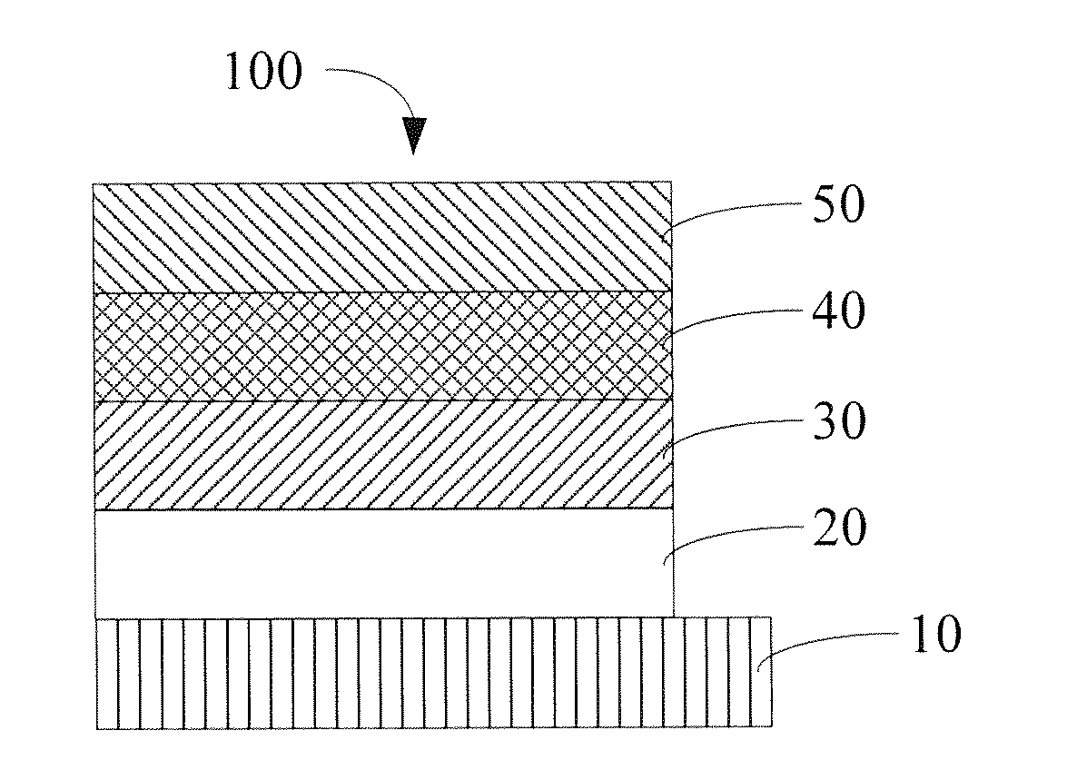
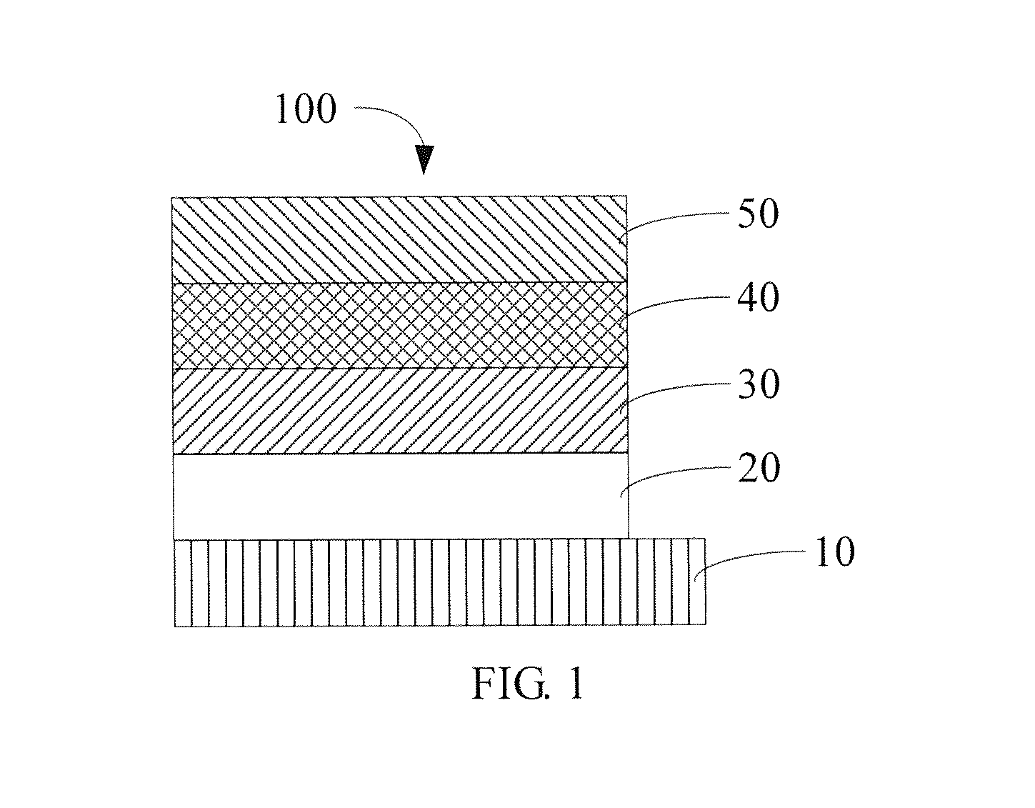
[0084]The embodiment of the polymer solar cell device has a structure of ITO / (PEDOT:PSS) / (MEH-PPV:PCBM) / (Bhpen:Cs2CO3:Ag) / Al.

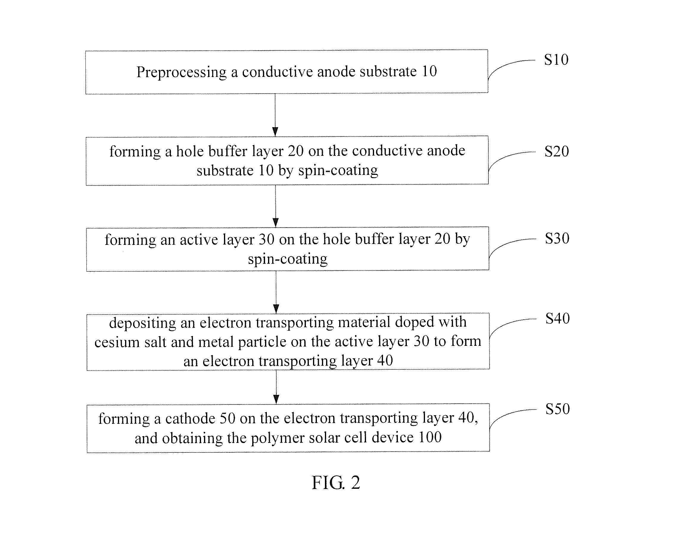
[0085]The preparation process of the polymer solar cell device is described as follows:

[0086]The ITO was photoetched and cut into pieces with required size, the ITO was then treated using ultrasonic sequentially in detergent, deionized water, acetone, ethanol, and isopropyl alcohol each for 15 minutes to remove organic pollutants on the surface of the glass. The ITO was treated with oxygen plasma for 5 minutes after cleaning; the power was 30 W. A solution of PEDOT and PSS was spin-coated on the ITO, a mass ratio of PEDOT to PSS was 6:1, a mass percent of the solution was 1.3%; and then heated at a temperature of 200° C. for 30 minutes, a hole buffer layer with a thickness of 40 nm was formed. Then, under a nitrogen atmosphere, a chlorobenzene solution of MEH-PPV and PCBM was spin-coated on the hole buffer layer, a mass ratio of MEH-PPV to PCBM was 1:3, a tota...

example 2

[0092]The embodiment of the polymer solar cell device has a structure of IZO / (PEDOT:PSS) / (MDMO-PPV:PCBM) / (PBD:CsF:Al) / Ag.

[0093]The preparation process is described as follows:

[0094]The IZO was photoetched and cut into pieces with required size, the IZO was then treated using ultrasonic sequentially in detergent, deionized water, acetone, ethanol, and isopropyl alcohol each for 15 minutes to remove organic pollutants on the surface of the glass, respectively. The IZO was treated with oxygen plasma for 5 minutes after cleaning; the power was 30 W. A solution of PEDOT and PSS was spin-coated on the IZO, a mass ratio of PEDOT to PSS was 2:1, a mass percent of the solution was 5%; and then heated at a temperature of 100° C. for 60 minutes, a hole buffer layer with a thickness of 20 nm was formed. Then, under an argon atmosphere, an xylene solution of MEH-PPV and PCBM was spin-coated on the hole buffer layer, a mass ratio of MEH-PPV to PCBM was 1:4, a total concentration of the xylene sol...

example 3

[0095]The embodiment of the polymer solar cell device has a structure of AZO / (PEDOT:PSS) / (P3HT:PCBM) / (TPBi:CsCl:Au) / Pt.

[0096]The preparation process is described as follows:

[0097]The AZO was photoetched and cut into pieces with required size, the AZO was then treated using ultrasonic sequentially in detergent, deionized water, acetone, ethanol, and isopropyl alcohol each for 15 minutes to remove organic pollutants on the surface of the glass, respectively. The AZO was treated with UV-ozone treatment for 15 minutes after cleaning. A solution of PEDOT and PSS was spin-coated on the AZO, a mass ratio of PEDOT to PSS was 4:1, a mass percent of the solution was 1%; and then heated at a temperature of 200° C. for 15 minutes, a hole buffer layer with a thickness of 80 nm was formed. Then, under a helium atmosphere, an xylene solution of P3HT and PCBM was spin-coated on the hole buffer layer, a mass ratio of P3HT to PCBM was 1:0.8, a total concentration of the xylene solution was 30 mg / mL, ...


PUM

PropertyMeasurementUnit
particle sizeaaaaaaaaaa
thicknessaaaaaaaaaa
mass ratioaaaaaaaaaa

Abstract

Provided are a polymer solar cell (100) and a method for preparing the same. The solar cell (100) comprises the following structures: a conductive anode substrate (10), a hole buffer layer (20), an active layer (30), an electron transportation layer (40) and a cathode (50); and the material for the electron transportation layer (40) is an electron transportation material doped with a cerium salt and metal particles. The solar cell (100) effectively increases the rate of electron transportation, and decreases the potential barrier between the electron transportation layer (40) and the cathode (50).

Description

FIELD OF THE INVENTION[0001]The present disclosure relates to a field of solar cell, and more particularly relates to a polymer solar cell device and a method for preparing the same.BACKGROUND OF THE INVENTION[0002]In 1982, Weinberger et al. researched the photovoltaic properties of polyacetylene and prepared the first true sense of solar cell, while the energy conversion efficiency of the solar cell is very low (10−3%). Subsequently, Glenis et al. prepared a variety of solar cells of polythiophene, but these solar cells had problems of very low open circuit voltage and photoelectric conversion efficiency. Until 1986, C. W. Tang et al. introduced the p-type semiconductor and the n-type semiconductor into devices of bilayer structure for the first time, the level of the photocurrent had been improved greatly, and the organic polymer solar cells had flourished since this work which is regarded as a milestone.[0003]In 1992, Sariciftci et al. found that there was a phenomenon of rapid l...

Claims


Application Information

Patent Timeline
Patent Type & Authority Applications(United States)
IPC IPC(8): H01L51/00H01L51/44
CPCH01L51/0037H01L51/44H01L51/007H01L51/0072H01L2051/0063H01L51/0036H01L51/0047H01L51/0038H01L51/0003H01L51/0067H10K30/30H10K2102/00Y02E10/549H10K71/12H10K85/114H10K85/215H10K85/654H10K30/35H10K30/353H10K85/1135H10K30/80H10K85/113H10K85/6565H10K85/6572
Inventor ZHOU, MINGJIEWANG, PINGHUANG, HUICHEN, JIXING
Owner OCEANS KING LIGHTING SCI&TECH CO LTD
Why Eureka
Try Eureka