
Piezoelectric material, piezoelectric element, and electronic device

Active Publication Date: 2015-01-15
CANON KK
View PDF1 Cites 13 Cited by
  • Summary
  • Abstract
  • Description
  • Claims
  • Application Information

AI Technical Summary

Benefits of technology

The present invention is about a new piezoelectric material that has several advantages. Firstly, it does not contain any harmful materials like lead. Secondly, it has a small change in its electrical properties with temperature changes. Thirdly, it is dense and has a high quality factor, which indicates its ability to vibrate with high efficiency. Finally, its piezoelectric constant is satisfactory. This material can help reduce environmental pollution as it does not contain any harmful components.

Problems solved by technology

However, a lead component is harmful to the ecological system because there is a possibility that the lead component of a wasted piezoelectric material may dissolve into the soil.
If a parameter relating to the piezoelectric performances, e.g., an electromechanical coupling factor, dielectric constant, a Young's modulus, a piezoelectric constant, a mechanical quality factor, or resonance frequency, greatly changes (for example, by an amount equivalent to 30% or more) depending on the temperature, it becomes difficult to obtain stable element performances in the operating temperature range.
If the mechanical quality factor is low, an amount of electric power required to operate a piezoelectric element becomes higher and a driving control of the piezoelectric element becomes difficult due to heat generation.
Therefore, although the above-mentioned piezoelectric material demonstrates excellent piezoelectric performances around the room temperature, it is not desired that the piezoelectric performances is remarkably variable depending on the temperature.
However, according to an evaluation result, the above-mentioned piezoelectric material is not desired in that the temperature at which a phase transition occurs between the tetragonal and the orthorhombic is in a range from 5° C. to −20° C. Further, the above-mentioned piezoelectric material is not desired in that the mechanical quality factor at the room temperature is low (less than 500).
The above-mentioned conventional non-lead piezoelectric ceramics is not desired in that the piezoelectric performances greatly vary in the operating temperature range of a piezoelectric element and the mechanical quality factor is small.

Method used


Image

  • Piezoelectric material, piezoelectric element, and electronic device
  • Piezoelectric material, piezoelectric element, and electronic device
  • Piezoelectric material, piezoelectric element, and electronic device

Examples


example 55

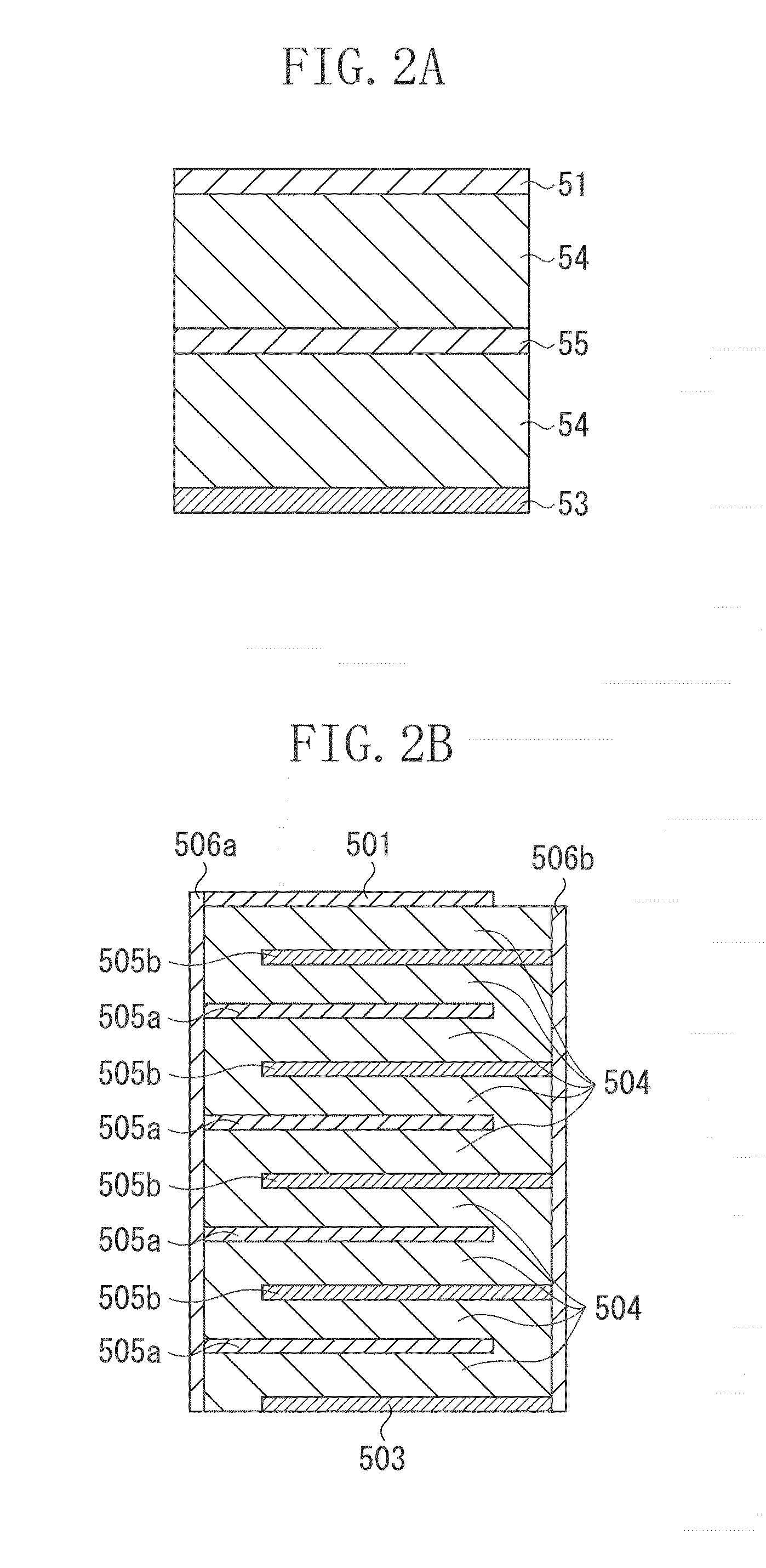
[0211]The weighing of barium titanate (BaTiO3), calcium titanate (CaTiO3), calcium zirconate (CaZrO3), lithium carbonate (Li2CO3), bismuth oxide (Bi2O3), tetramanganese trioxide (Mn3O4), and glass assistant containing Si and B (including SiO2 by 30 to 50 wt. % and B2O3 by 21.1 wt. %) has been performed for a test piece in such a way as to attain the composition of the example 48 described in the table 3. The weighed raw material powder has been mixed in the ball mill for a night to obtain a mixed powder.

[0212]Then, the obtained mixed powder has been mixed with an additive of PVB and formed into a green sheet having a thickness of 50 μm according to a doctor blade method.

[0213]Then, to form an internal electrode, an electrically conductive paste has been printed on the above-mentioned green sheet. The electrically conductive paste used in this case is an alloy paste containing Ag 60%-Pd 40%. Then, a multilayered body has been obtained by successively stacking nine green sheets with t...

example 56

[0217]A mixed powder has been fabricated by using a method similar to that of the example 55. Then, a calcined powder has been obtained by performing calcination in the atmosphere at 1000° C. for three hours while rotating the obtained mixed powder in a rotary kiln. Then, the obtained calcined powder has been cracked in the ball mill. Then, the obtained cracked powder has been mixed with an additive of PVB and formed into a green sheet having a thickness of 50 μm according to the doctor blade method. Then, to form an internal electrode, an electrically conductive paste has been printed on the above-mentioned green sheet. The electrically conductive paste used in this case is a Ni paste. Then, a multilayered body has been obtained by successively stacking nine green sheets with the electrically conductive paste applied thereon. Then, the obtained multilayered body has been subjected to thermocompression bonding.

[0218]Further, the thermocompression-bonded multilayered body has been si...

example 57

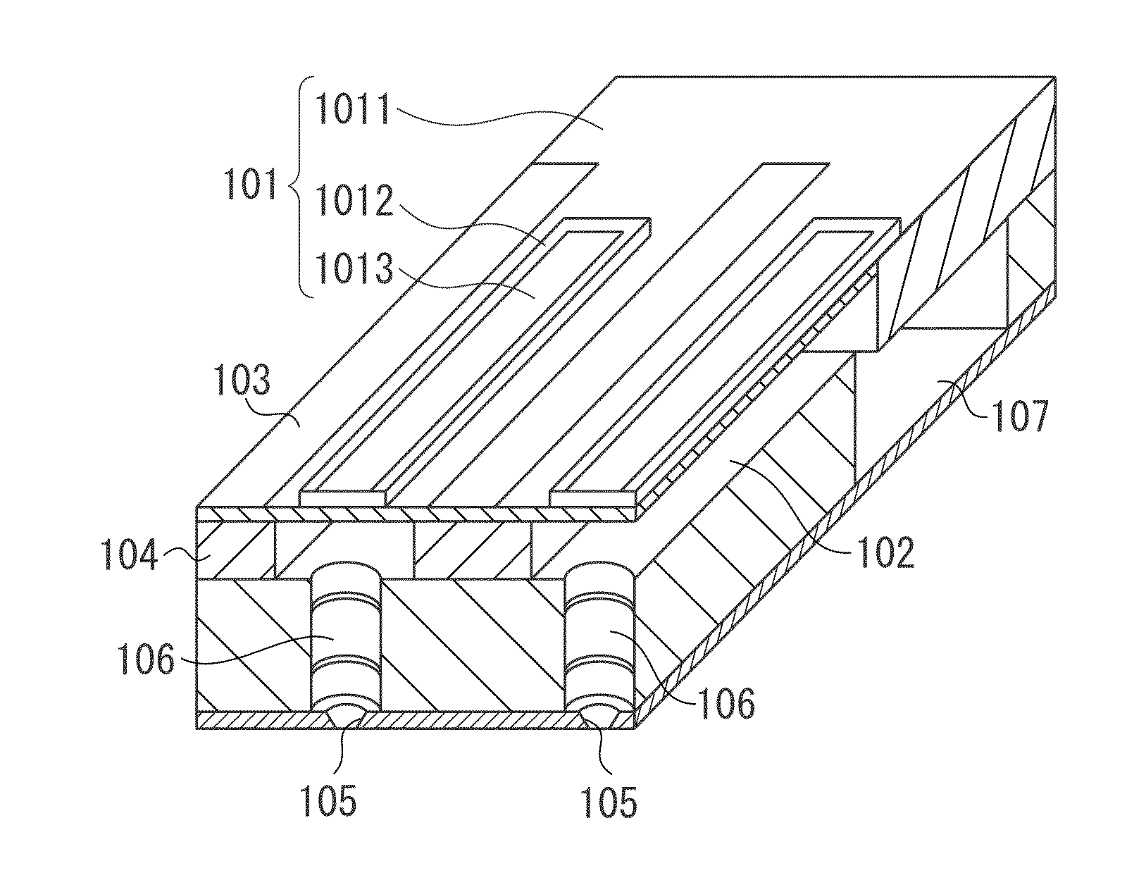
[0221]The piezoelectric element of the example 20 has been used to fabricate the liquid discharge head illustrated in FIG. 3. It has been confirmed that the fabricated liquid discharge head can discharge an ink according to an input electric signal.


PUM

PropertyMeasurementUnit
Temperatureaaaaaaaaaa
Percent by massaaaaaaaaaa

Abstract

There is provided a piezoelectric material not containing any lead component, having stable piezoelectric characteristics in an operating temperature range, a high mechanical quality factor, and satisfactory piezoelectric characteristics. The piezoelectric material includes a main component containing a perovskite-type metal oxide that can be expressed using the following general formula (1), and subcomponents containing Mn, Li, and Bi. When the metal oxide is 100 parts by weight, the content of Mn on a metal basis is not less than 0.04 parts by weight and is not greater than 0.36 parts by weight, content α of Li on a metal basis is not less than 0.0013 parts by weight and is not greater than 0.0280 parts by weight, and content β of Bi on a metal basis is not less than 0.042 parts by weight and is not greater than 0.850 parts by weight(Ba1-xCax)a(Ti1-y-zZrySnz)O3  (1)(in the formula (1), 0.09≦x≦0.30, 0.074<y≦0.085, 0≦z≦0.02, and 0.986≦a≦1.02)

Description

BACKGROUND OF THE INVENTION[0001]1. Field of the Invention[0002]The present invention relates to a piezoelectric material, more specifically, to a piezoelectric material that does not contain any lead component. Further, the present invention relates to a piezoelectric element, a multilayered piezoelectric element, a liquid discharge head, a liquid discharge apparatus, an ultrasonic motor, an optical device, a vibrating apparatus, a dust removing apparatus, an imaging apparatus, and an electronic device, in which the piezoelectric material is employed.[0003]2. Description of the Related Art[0004]A lead zirconate titanate is a representative lead-containing piezoelectric material, which can be used in various piezoelectric devices, such as an actuator, an oscillator, a sensor, and a filter. However, a lead component is harmful to the ecological system because there is a possibility that the lead component of a wasted piezoelectric material may dissolve into the soil. Accordingly, res...

Claims


Application Information

Patent Timeline
IPC IPC(8): H01L41/18
CPCH01L41/183C04B35/49C04B2235/3208C04B2235/3205C04B35/4682B41J2/14233B41J2202/03G02B7/04H02N2/163G02B27/0006G02B15/02H02N2/106G03B3/10H04N23/663H10N30/8536H10N30/2047H10N30/50H10N30/852
Inventor WATANABE, TAKAYUKITANAKA, HIDENORIMURAKAMI, SHUNSUKEFURUTA, TATSUOYABUTA, HISATO
Owner CANON KK
Learn More