Fabrication and application of nanofiber ribbons and sheets and twisted and non-twisted nanofiber yarns

a technology of nanofiber ribbons and nanofiber yarns, which is applied in the direction of secondary cells, chemical vapor deposition coatings, energy inputs, etc., can solve the problems of inability to achieve significant tensile strength in applications such as these and other nanofibers, and the viscosity of melts becomes too high for conventional melts or solution spinning, etc., to achieve high electrical and thermal conductivity, high energy absorption, and extreme toughness

Active Publication Date: 2015-10-29
BOARD OF RGT THE UNIV OF TEXAS SYST
View PDF4 Cites 22 Cited by
  • Summary
  • Abstract
  • Description
  • Claims
  • Application Information

AI Technical Summary

Benefits of technology

[0029]Prior to or after yarn collection, twist in one direction in a singles yarn can be compensated by twist in an opposite direction at another stage in processing for a variety of useful purposes, such as for (a) plying yarns by folding them onto themselves and (b) forming composite or welded structures in which the nanotubes are untwisted or minimally twisted. The benefits provided by the initially introduced twist can be yarn densification and / or increases in yarn strength that enable application of increased forces on the yarn during initial processing.
[0034]In some embodiments, the present invention is directed to an apparatus for producing a nanofiber ribbon or sheet, the apparatus operable to perform a process comprising the steps of: (a) arranging nanofibers to provide a substantially parallel nanofiber array having a degree of inter-fiber connectivity within the nanofiber array; and (b) drawing said nanofibers from the nanofiber array as a ribbon or sheet without substantially twisting the ribbon or sheet, wherein the ribbon or sheet is at least about one millimeter in width.
[0038]In some embodiments, the present invention is directed to a process for making a deformable nanofiber sheet or ribbon comprising the steps of: (a) selecting a substrate from the group consisting of an elastically deformable substrate, an electrically deformable substrate, and combinations thereof; (b) elongating the substrate to form a deformed substrate, wherein said elongation is selected from the group consisting of elastically elongating, electrically elongating, and combinations thereof; (c) adhesively applying a nanofiber sheet or ribbon to the deformed substrate; and (d) enabling at least partial return of said elongation after said adhesive application step.
[0039]In some embodiments, the present invention is directed to a process for embedding an elastomerically deformable nanofiber sheet between two elastomeric polymer sheets comprising: (a) selecting a first elastomeric polymer sheet; (b) elastically elongating the first elastomeric polymer sheet to form a deformed substrate; (c) adhesively applying a nanofiber sheet to the deformed substrate; (d) enabling at least partial return of said elastic elongation after said adhesive application step; (e) applying a resin precursor for a second elastomeric polymer sheet to the nanofiber sheet when the first elastomer polymer sheet is in relaxed or partially relaxed state; and (f) curing the resin precursor to form the second elastomeric polymer sheet while the first elastomer polymer sheet is in a relaxed or partially relaxed state.
[0058]In some embodiments, the nanotube yarns comprise carbon nanotubes. Such carbon nanotube yarns of the present invention provide unique properties and property combinations such as extreme toughness, resistance to failure at knots, high electrical and thermal conductivities, high absorption of energy that occurs reversibly, up to 13% strain-to-failure compared with the few percent strain-to-failure of other fibers with similar toughness, very high resistance to creep, retention of strength even when heated in air at ˜450° C. for one hour, and very high radiation and UV resistance, even when irradiated in air. Furthermore, these nanotube yarns can be spun as one micron diameter yarns and plied at will to increase the linear density (i.e., the weight per yarn length) by forming two-folded, four-folded, and multi-folded yarns.

Problems solved by technology

A critical problem hindering applications of these and other nanofibers is the need for methods for assembling these nanofibers into long yarns, sheets, and shaped articles that effectively utilize the properties of the nanofibers.
However, the resulting assemblies are extremely weak, so they cannot be used for applications that require any significant level of tensile strength.
Although advances have been made in spinning polymer solutions or polymer melts containing either SWNTs or MWNTs, the melt viscosity becomes too high for conventional melt or solution spinning when the nanotube content is much above 10%.
Another problem with both polymer melt and polymer solution spinning is that the nanotubes are not present in sufficient quantities in the polymer to effectively contribute to such properties as thermal and electrical conductivities.
Even after this CVD coating process, the hollow nanotube yarns had low strength and low modulus and were quite brittle (see Lobovsky et al. in U.S. Pat. No. 6,682,677).
Present problems with this process result from the fact that the nanotubes are simultaneously assembled in combination with poly(vinyl alcohol) (PVA) to form gel fibers, which are converted to solid nanotube / PVA fibers.
This PVA then interferes with electrical and thermal contact between carbon nanotubes.
The PVA can be removed by thermal pyrolysis, but this severely degrades the mechanical properties of the fibers.
Unfortunately, the polymer-containing fibers made by the above gel spinning processes are not useful for applications as electrodes immersed in liquid electrolytes because they swell dramatically (by 100% or more) and lose most of their dry-state modulus and strength.
This process means that these polymer-containing fibers are unusable for critically important applications that use liquid electrolytes, such as in supercapacitors and in electromechanical actuators (R. H. Baughman, Science 290, 1310 (2000)).
Though highly electrically conductive (W. Zhou et al., Journal of Applied Physics 95, 649 (2004)), such prepared yarns have compromised properties, in part due to partial degradation of SWNTs caused by prolonged contact with sulfuric acid.
This degradation, which can be partially reversed by high temperature thermal annealing in vacuum, creates a serious obstacle for practical applications.
Moreover, any solution- or melt-based processing method that directly forms a polymer assembly is limited to short nanotube lengths (typically a few microns) by the viscosity increases associated with polymer dispersion and formation of globules having little nanotube orientation as a result of nanotube coiling.
While a twisted yarn was pictured, the ratio of nanotube length (˜30 μm) to yarn diameter was about unity, which means that important property enhancements due to lateral forces generated by twisting were not obtainable.
However, no successful means has been conceived in the prior art for achieving the potential benefits of yarn twisting for nanofibers that are a thousand-fold or more smaller in diameter than for the twisted yarns of the prior art.
Reflecting these problems with prior-art technologies of nanofiber yarns, important applications have not yet been commercially enabled, such as carbon nanotube artificial muscles (R. H. Baughman et al., Science 284, 1340 (1999) and U.S. Pat. No. 6,555,945), carbon nanotube yarn supercapacitors, structural composites involving carbon nanotubes, and electronic textiles involving strong, highly conducting nanofiber yarns,
All of these processing methods are liquid based, and none provides strong, transparent, nanofiber electrode materials or those that can be self-supporting when transparent.
Also, none of these methods provides nanotube-based electrodes having useful anisotropic in-plane properties, like anisotropic electrical and thermal conductivity and the ability to polarize light.
However, strong, transparent nanofiber electrodes have not been available for use in dye solar cells (DSCs), although the need for them is apparent, particularly for flexible solid-state DSCs.
Additionally, none of the above-mentioned approaches have addressed the problem of charge collection or injection from such transparent CNT coatings into organic electronic devices: organic light emitting diodes (OLEDs), optical field effect transistors (OFETs), solar cells, etc.
This problem requires either very low work function (w.f.) for electron injection or high w.f. for hole injection.
However, the resulting forest assemblies have various instabilities at large current loads, one such instability being the flash evaporation of catalyst and carbon, followed by spark emission of light and by the transfer of CNTs from cathode to anode, thereby destroying the cathode (R. Nanjundaswamy et. al., in Functional Carbon Nanotubes, edited by D. Carroll et al.
Although advances have been made in creating robust forests of oriented CNTs on glass substrates (e.g., by Motorola and Samsung), such forests are still not the best solution for the nanofiber cold cathode.
One of the most challenging issues with oriented CNT arrays is the emission non-uniformity.
Due to problems with screening effects and variations in CNT structure and overall sample uniformity, only a very small fraction of the CNTs emit at any given time.
However, the same problems that exist for oriented forests of CNTs also exist in these types of emitters.
The problem with polymer binder / CNT cathodes is that the nanotubes are not present in sufficient quantities in the polymer to effectively contribute to field electron emission and also to such properties as thermal and electrical conductivities (so that the binder is destroyed by heat and current).
A critical problem hindering applications of these carbon nanotubes (CNT) cold cathodes is the need for methods of assembling these nanotubes into the framework of a macroscopic mounting system that is sufficiently strong and suitably shaped such that the properties of the CNTs for field emission can be effectively utilized.

Method used


Image

  • Fabrication and application of nanofiber ribbons and sheets and twisted and non-twisted nanofiber yarns
  • Fabrication and application of nanofiber ribbons and sheets and twisted and non-twisted nanofiber yarns
  • Fabrication and application of nanofiber ribbons and sheets and twisted and non-twisted nanofiber yarns

Examples


example 1

[0680]This example describes a typical method for growing nanotube forests used for selected invention embodiments. Aligned MWNT arrays (nanotube forests) were synthesized by atmospheric pressure CVD (Chemical Vapor Deposition) in a 45 mm diameter quartz tube using 5 molar percent C2H2 in He at 680° C., at a total flow rate of 580 sccm for 10 minutes. The catalyst was a 5 nm thick iron film that was deposited on a Si wafer substrate or glass substrate by electron beam evaporation. Based on SEM and thermal gravimetric measurements, the purity of the spun yarns was very high (˜96-98% C in the form of MWNTs), with 2-4% Fe and amorphous carbon and no observed carbon particles.

example 2

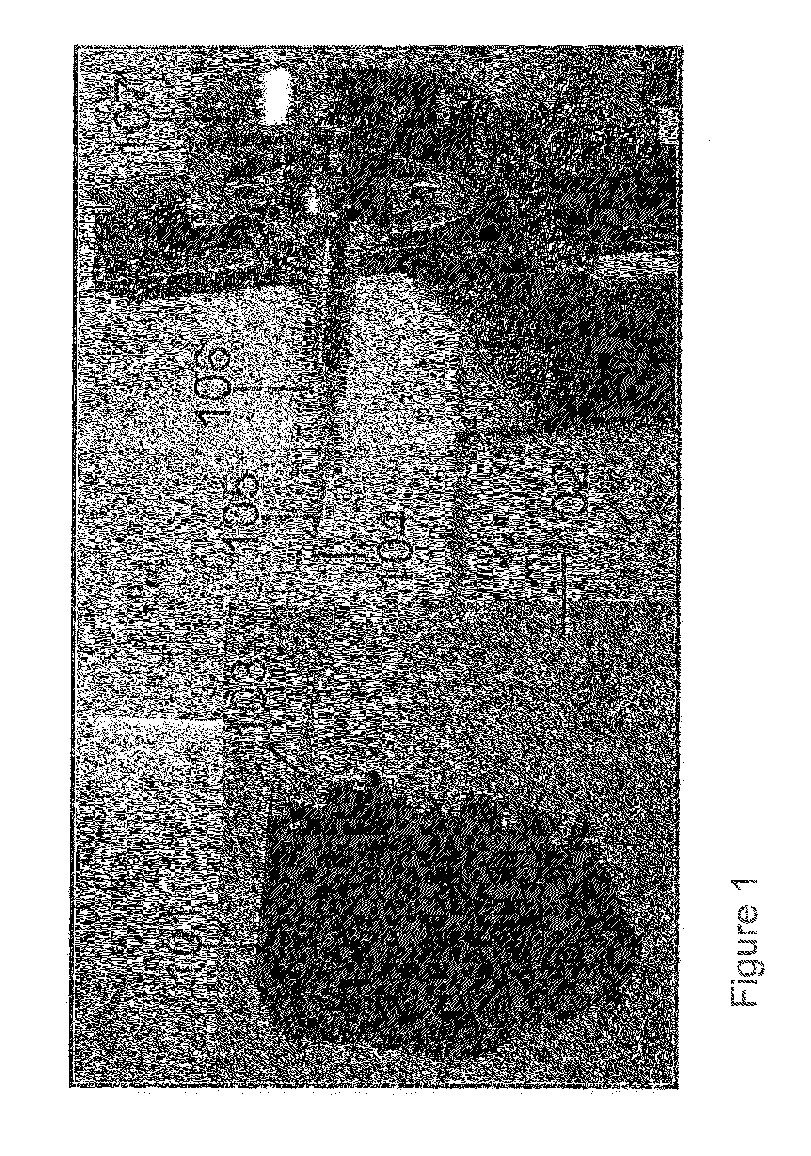
[0681]This example describes a method of invention embodiments for the introduction of twist during the spinning of carbon nanotubes from a nanotube forest. Previous attempts to draw yarns from nanotube forests resulted in extremely weak assemblies (see K. Jiang, Q. Li, and S. Fan in Nature 419, 801 (2002) and in U.S. Patent Application Publication No. 20040053780 (Mar. 18, 2004)). The present inventors find that simultaneously applied draw and twist processes increase the mechanical strength by a factor of over a thousand. The present inventors also show that the present spin-twist process is able to produce yarns even smaller than one micron in diameter. The fibers of this example were hand drawn during twisting by attaching nanotubes from the side of the nanotube forest of Example 1 to a probe tip that is coaxially attached to the axis of a variable speed motor that was typically operated at about 2000 rpm. In this example, illustrated by the photograph in FIG. 1, attachment was ...

example 3

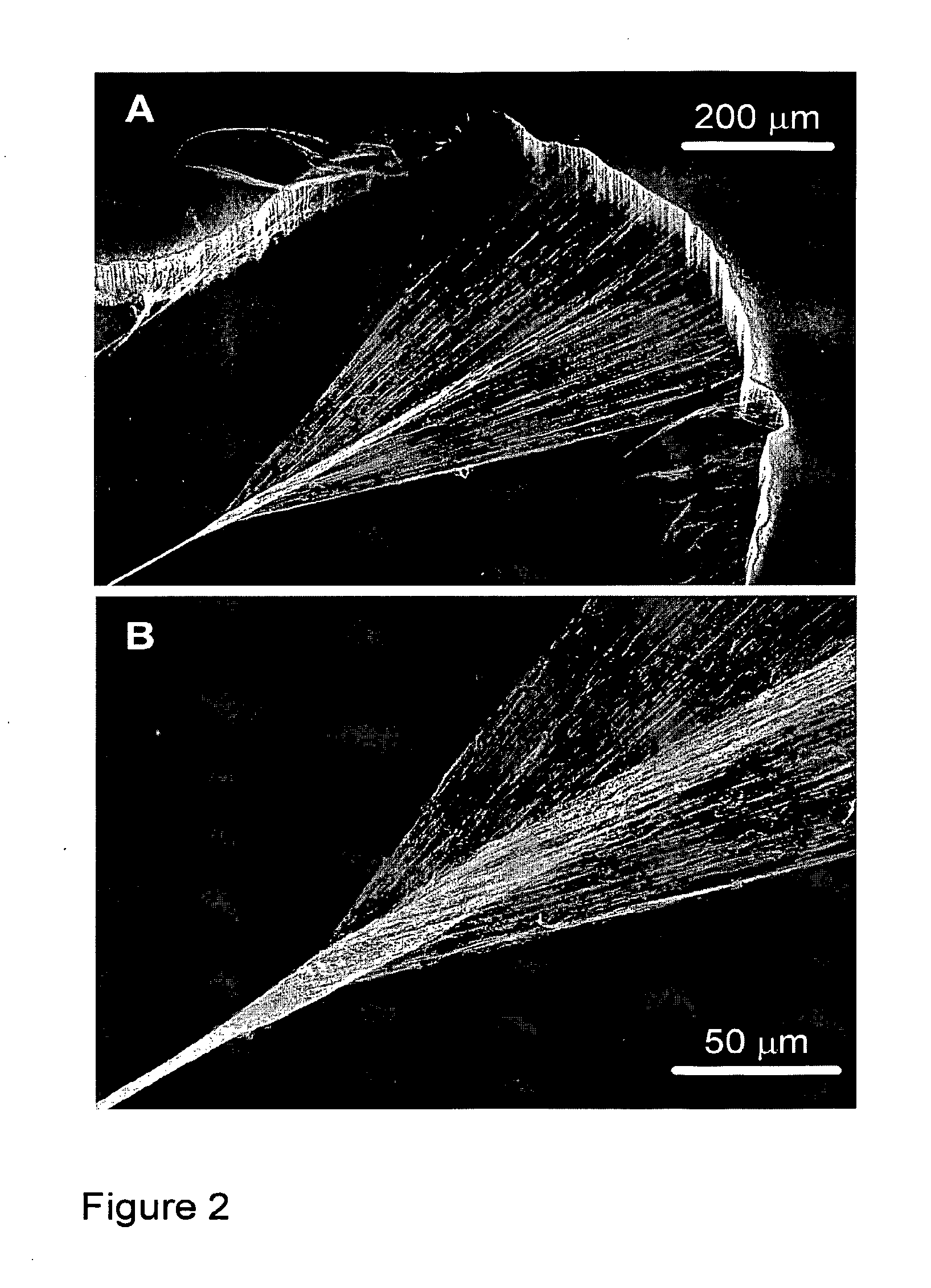
[0682]This example shows that extremely small diameter yarns can be spun using the method of Example 2. The yarn diameter was determined by controlling the width of the MWNT forest array that was pulled to generate the initial wedge-shaped untwisted ribbon that converged from a thickness of about the height of the forest to the width of the yarn at the wedge apex (FIG. 2). The array width ranged from below 150 μm to about 3 mm to produce singles yarn diameters of between about one and ten microns. A 200 μm wide forest array segment produced about a 2 μm diameter twisted yarn and a forest area of 1 cm2 could generate an estimated 50 m of this yarn. The inserted twist was typically about 80,000 turn / m, versus about 1000 turns / m for a conventional weaving textile yarn having 80 times larger diameter. The twist resulted in densities for the MWNT yarns of about 0.8 g / cm3, based on direct measurements of yarn mass, length, and yarn diameter, the latter being measured by SEM. The linear de...


PUM

PropertyMeasurementUnit
widthaaaaaaaaaa
thicknessaaaaaaaaaa
widthaaaaaaaaaa

Abstract

The present invention is directed to nanofiber yarns, ribbons, and sheets; to methods of making said yarns, ribbons, and sheets; and to applications of said yarns, ribbons, and sheets. In some embodiments, the nanotube yarns, ribbons, and sheets comprise carbon nanotubes. Particularly, such carbon nanotube yarns of the present invention provide unique properties and property combinations such as extreme toughness, resistance to failure at knots, high electrical and thermal conductivities, high absorption of energy that occurs reversibly, up to 13% strain-to-failure compared with the few percent strain-to-failure of other fibers with similar toughness, very high resistance to creep, retention of strength even when heated in air at 450° C. for one hour, and very high radiation and IJV resistance, even when irradiated in air. Furthermore these nanotube yarns can be spun as one micron diameter yarns and plied at will to make two-fold, four-fold, and higher fold yarns. Additional embodiments provide for the spinning of nanofiber sheets having arbitrarily large widths. In still additional embodiments, the present invention is directed to applications and devices that utilize and / or comprise the nanofiber yarns, ribbons, and sheets of the present invention.

Description

CROSS-REFERENCE TO RELATED APPLICATIONS[0001]This application for patent claims priority to the following U.S. Provisional Patent Applications: 60 / 626,314, filed Nov. 9, 2004; 60 / 666,351, filed Mar. 30, 2005; and 60 / 702,444, filed Jul. 26, 2005.[0002]This work was supported by Defense Advanced Research Projects Agency / US Army Research Office grant W911NF-04-1-0174, the Texas Advanced Technology Program grant 009741-0130-2003, and the Robert A. Welch Foundation.FIELD OF THE INVENTION[0003]Methods and apparatus are described for spinning high performance twisted, false twisted and non-twisted yarns comprising nanofibers and for drawing sheets and ribbons comprising nanofibers. Shaped articles, composites, and applications are described for these yarns, ribbons, and sheets.DESCRIPTION OF THE BACKGROUND ART[0004]Commercial synthesis methods produce nanofibers of either carbon single wall nanotubes (SWNTs) or carbon multiwalled nanotubes (MWNTs) as a soot-like material. The strength and ...

Claims


Application Information

Patent Timeline
Patent Type & Authority Applications(United States)
IPC IPC(8): D01F9/12D01F9/127C01B31/02
CPCD01F9/12D01F9/127C01B31/0293B01L3/502707B82Y10/00C04B35/62231C04B35/62272C04B35/62281C04B35/62855C04B35/62892C04B35/62897D02G3/16D02G3/28H01G11/36D01F9/1275D10B2101/122H01M4/8605G02F1/15165C04B2235/526C04B2235/5264C04B2235/5248C04B2235/422H10K85/221H10K50/81H10K50/828Y02E10/549C01B32/164Y10T428/30B29C48/0019Y10S977/752Y10S977/746H01B1/24Y10S977/932Y10S977/844Y10S977/948Y10S977/961Y10S977/742Y10S977/745Y10S977/843Y10S977/847Y10S977/848C01B32/18C01B32/168C01B32/16Y02P20/133Y02P70/50Y02E60/50Y02E60/10H10K30/821D02G3/02D01H7/00Y02E60/13G02F1/133334H10K50/30D04H3/002D06B15/00B32B37/12B32B2307/202C23C16/50B82Y30/00B82Y40/00C01B2202/06G01L1/2287G02F1/133308H01B5/08H05K9/0081C01B2202/08D01F9/1273D06M15/256D06M15/333C04B35/80C04B2235/616C23C16/44D01F9/08H01M4/926H01M10/0565B32B5/02B32B5/12B32B2262/106B32B18/00B32B2310/00B32B2313/04D02G3/44C01B32/158C01B32/17C01B32/15C01B32/154C01B32/36
Inventor ZHANG, MEIFANG, SHAOLIBAUGHMAN, RAY H.ZAKHIDOV, ANVAR A.ATKINSON, KENNETH ROSSALIEV, ALI E.LI, SERGEYWILLIAMS, CHRIS
Owner BOARD OF RGT THE UNIV OF TEXAS SYST
Why Eureka
Try Eureka