Efficiency and emissions improvements for natural gas conversions of emd 2-cycle medium speed engines

a technology of natural gas conversion and emission reduction, applied in the direction of engines, machines/engines, mechanical apparatus, etc., can solve the problems of increasing engine thermal efficiency, reducing efficiency, and difficult packaging of single large substrates, so as to reduce the effectiveness of multiple ignition points, reduce the effect of distance into the combustion chamber, and reduce the effect of

Inactive Publication Date: 2016-01-07
RAIL PROPULSION SYSTEMS LLC
View PDF3 Cites 17 Cited by
  • Summary
  • Abstract
  • Description
  • Claims
  • Application Information

AI Technical Summary

Benefits of technology

[0082]In order to adequately capture the effect of TJI, the orifice has to be small enough to quench the burning air and fuel mixture as it exits the prechamber passing thought the orifices. In order to do this, orifices as small as 0.050 inch diameter may be needed. As the size of the orifice gets smaller, the prechamber jets will penetrate less distance into the combustion chamber and have a reduced effect in two ways. First the ignition will happen closer to the center of the combustion chamber reducing the effectiveness of the multiple ignition points to decrease the total burn duration.
[0083]The second negative effect of the smaller orifice jet is that there will be less accumulated partially burned air and fuel in the pockets that are formed by the small jets. These pockets of combustion radicals may end up being dilute enough or in a small enough local quantity to not ignite consistently or ignite with enough energy to initiate rapid combustion of the lean air fuel mixture around the pocket. Proposed is to have groups of a higher number of smaller nozzles configured so that two or more nozzles converge in the combustion chamber. This will help over come the penetration and concentration issues with smaller nozzles while keeping the delayed combustion benefits of the smaller nozzle quenching effects on delayed combustion for more rapid heat release rates.

Problems solved by technology

This led to an actual increase of engine thermal efficiency at some points even though the additional back pressure of the OC would typically cause a decrease in efficiency due to reduced airflow.
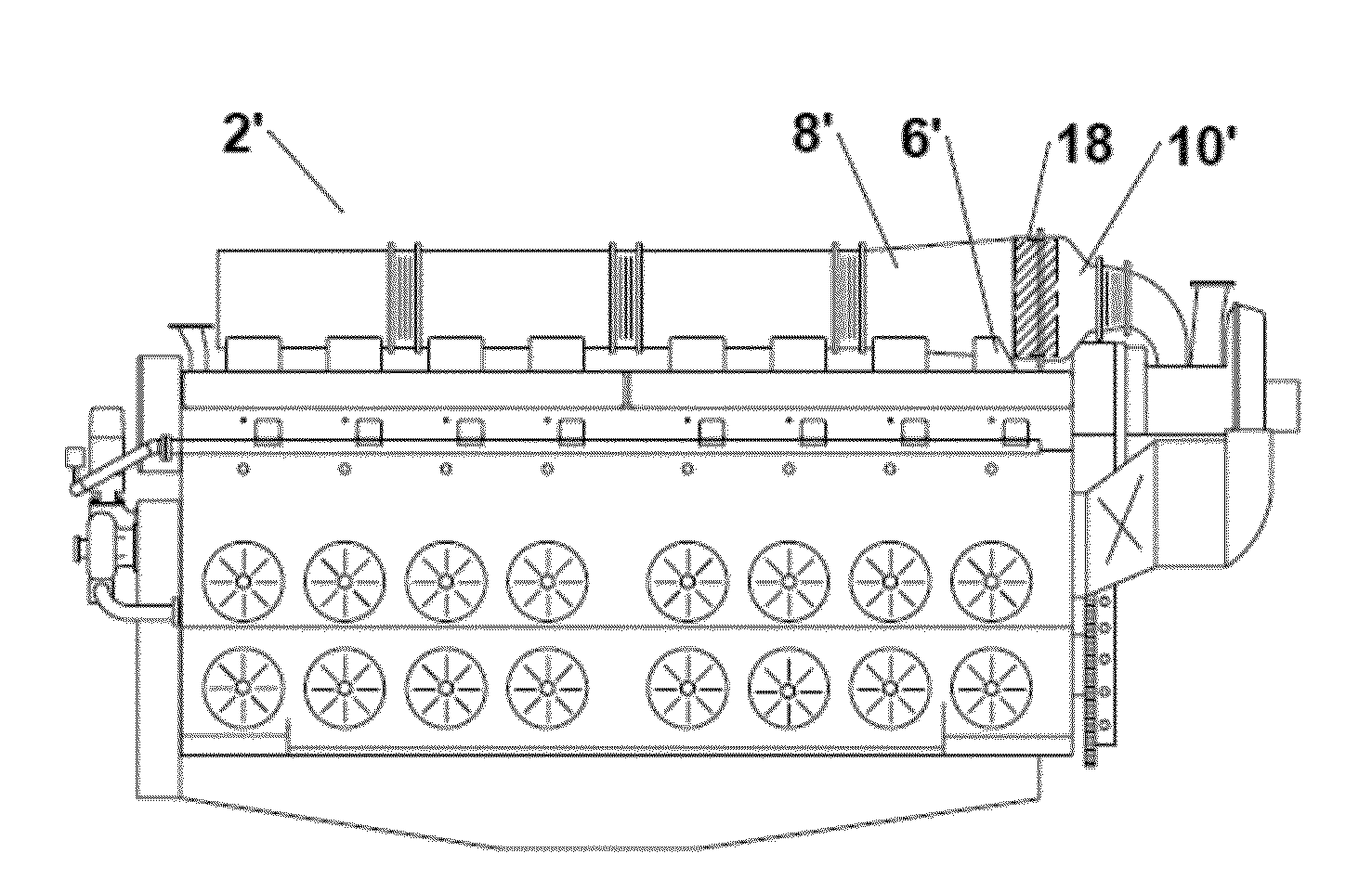
Because of the way the exhaust manifold segments are tightly packaged across the top of the engine and there is only a short 4 inch length of common exhaust plenum before the turbo charger inlet plumbing, there was no easy way to package a single large substrate that all of the exhaust would flow through equally.
If a single large substrate was attempted and each cylinder was affected differently, performance would suffer as some cylinders would get more intake air than others.
While accurately measured, this pressure drop is not representative of the instantaneous pressure drop that affects the scavenging of the cylinder and how much intake air is brought into the cylinder.
Early versions of this single substrate per cylinder OC system suffered substrate failures that were attributed to the pulsing effect of the exhaust gases flowing rapidly through the substrate for only ⅓ of the crank rotation.
Further the NOx reduction efficiency of the Compact SCR system at throttle setting of idle through Notch 2 were very low.
On the other hand the low load reduction in SCR efficiency is because the engine air fuel ratio is becoming too lean and the exhaust temperature is very low.
Also at these lower loads the engine actually needs less air because it is making less power and consuming less fuel.
This causes the engine to take in even more air than is needed and this excess air in the combustion chamber lowers the exhaust temperature.
At idle this problem is at its worst as the low RPM allows a long time for scavenging and the minimal engine fuel consumption further drives down the exhaust temperature.
If the flow is swirling in the direction of the centrifugal impeller rotation then the amount of pressure rise across the impellor will decrease as the impellor will not be able to put as much work or energy into the flow.
This would increase the amount of work or energy that the impellor will impart into the airflow increasing the pressure rise.
If the centrifugal impellor was part of a turbocharger, this increase in pressure rise would result in slowing down the impeller and turbine.
At low loads this improved intake air cooling would exacerbate the low combustion temperature issues at lower throttle settings.
What this leads to is a mixing challenge where the air and fuel have limited time to mix as the piston rises up to top dead center right before ignition.
This mixing challenge is why SwRI on their single cylinder development EMD 710 engine decided to do premixing of the air and fuel even though it would not be practical on an ‘in service’ engine as too much unburned fuel would blow through the cylinder into the exhaust while scavenging.
The in cylinder mixing issue can make prechamber operation difficult if a rich pocket of air and gas gets pushed into the prechamber which already has excess fuel in it.
At these very high lambdas it would require a larger prechamber that will produce fewer NOx emissions and have a lower thermal efficiency.
When the inlet is throttled to help reduce the low load air fuel Lambda, a large portion of this mixing energy is lost.
First it has many machined parts with complicated features that will be costly.
Second, the design has a built in cavity where residual natural gas will be compressed into and remain unburned during the combustion event.
This release of unburned methane is both a pollution emissions problem and an energy efficiency problem.
The cooling of a prechamber is one of the challenges, and the most challenging part of the prechamber to cool is the nozzle or tip area.
With insufficient cooling it has been documented that overheating prechambers will often melt the tip of the prechamber.
Sometime before the tip actually melts, it will cause preignition which will limit how much power the engine can produce or cause the engine to run improperly during some conditions.
This will cause the other cylinders to have to operate at a higher power to make up the lost power from the deactivated cylinders.
Because the prechamber is still fed fuel, but the main chamber is not, there is no guarantee that the mixture in the prechamber is being burned when a cylinder is deactivated, even when the spark plug is still being fired.
When the cylinder is deactivated the air pushed into the prechamber by the piston will not have any fuel so the overall mixture in the prechamber may be too lean for the spark to burn.
Because skip fire happens at low load it's likely that the extended time the system gets to fill the prechamber offsets this deactivated cylinder issue, but at the same time the operating cylinders are running richer and having the deactivated cylinders prechambers rich enough to fire may make the activated prechambers too rich causing misfires or combustion instability.
The generation of Non-Methane HC emissions is especially problematic as after the spark plug initiates combustion in the prechamber some unburned natural gas is pushed out of the prechamber into the main chamber before it is burned inside the prechamber.
There are several issues that make water injection not worth the effort of implementation in most mobile applications; one is the volume and weight of the consumable water and second is the need to refill the container that would store it.
Once these issues are overcome, then there is the environmental issue of keeping the stored onboard water from freezing when the vehicle is not in operation.
Another issue is the challenge of corrosion to the hardware that would be used to inject it, especially if the injector is designed to open and close rapidly for each cylinders combustion cycle.
Finally is the corrosion issue as related to any other parts.
If after shut down an injector would leak water into the engine cylinder during engine storage, that cylinder will have internal corrosion and suffer significant maintenance issues.
If it wasn't reduced the engine may be limited to only generation of 60% of its original diesel operation rated power.

Method used


Image

  • Efficiency and emissions improvements for natural gas conversions of emd 2-cycle medium speed engines
  • Efficiency and emissions improvements for natural gas conversions of emd 2-cycle medium speed engines
  • Efficiency and emissions improvements for natural gas conversions of emd 2-cycle medium speed engines

Examples


Embodiment Construction

[0116]To facilitate an understanding of the present disclosure, a number of terms and phrases are defined below:

[0117]Gaseous Fuel: The predominant gaseous fuel used in internal combustion engines is natural gas consisting mostly of methane, but with minor modifications these engines could consume any gaseous fuel including but not limited to propane, natural gas and hydrogen. In this document the term natural gas and gaseous fuel are used interchangeably.

[0118]Hydrocarbon (HC): Emissions resulting from incomplete combustion.

[0119]Main Charge: The air fuel mixture in the main combustion chamber space between the piston top and the cylinder head. If an opposed piston engine, this would be the space between the opposed piston faces.

[0120]Particulate Matter (PM): Particulate matter is a criteria pollution emitted from many sources. In this document we will commonly refer to it simply as PM. It could include both diesel soot PM that is considered toxic in California or the type of PM cr...


PUM


Abstract

A prechamber assembly includes a cylinder head including a coolant cavity, a prechamber body located within the cylinder head, the prechamber body including a nozzle, and an annular sleeve radially surrounding a portion of the prechamber body. The sleeve includes a plurality of coolant inlet holes. A portion of the prechamber body is radially spaced from the sleeve to form a coolant sleeve annulus extending along a length of the prechamber body above the coolant inlet holes. The coolant cavity and the coolant sleeve annulus are in fluid communication through the plurality of coolant inlet holes.

Description

CROSS-REFERENCE TO RELATED APPLICATIONS[0001]This application claims the benefit of priority to U.S. Provisional Application No. 62 / 049,651 filed on Sep. 12, 2014, and U.S. Provisional Application No. 62 / 128,296, filed Mar. 4, 2015, and is a continuation-in-part of U.S. application Ser. No. 14 / 217,058, filed Mar. 17, 2014, which claims the benefit of priority to U.S. Provisional Application No. 61 / 790,771 filed on Mar. 15, 2013, the disclosures of which are incorporated by reference herein.BACKGROUND OF THE INVENTION[0002]The first portion of the background is most closely related to a single element preturbine oxidation catalyst element for EMD turbocharged engines using twisted exhaust runners. Oxidation catalysts (OC) are used to reduce the emissions of unburned hydrocarbons (HC), carbon monoxide (CO) and certain types of particulate matter (PM). Of the aftertreatment systems used on lean burn engines, this is the simplest system as it is completely passive and practically mainte...

Claims


Application Information

Patent Timeline
Patent Type & Authority Applications(United States)
IPC IPC(8): F01N3/04F01P3/02
CPCF01N3/046F01N2260/024F01P3/02F01N3/103F01N3/2066F01N13/0093F01N13/10F01N13/107F01N13/1816F01N2340/02F01N2340/06F01N2590/02F01N2590/08F01N2610/02F02B19/1004F02B19/108F02B19/1085F02B19/12F02B19/18F02B37/24F02B43/00F02B2075/025F02M21/0215F02M21/0251F02M21/0269F02M21/0275F02M21/0281Y02T10/12Y02T10/30F01P3/16
Inventor COOK, DAVID
Owner RAIL PROPULSION SYSTEMS LLC
Why Eureka
Try Eureka