Energy storage devices and systems

a technology of energy storage and energy density, applied in the direction of nanobatteries, cell components, sustainable manufacturing/processing, etc., can solve the problems of requiring a large footprint, and reducing the energy density of the energy storage device, so as to achieve stable dispersion and stable nanoparticle dispersion

Inactive Publication Date: 2019-11-07
3DBATTERIES LTD
View PDF0 Cites 7 Cited by
  • Summary
  • Abstract
  • Description
  • Claims
  • Application Information

AI Technical Summary

Benefits of technology

[0155]In some embodiments, the dispersion comprises charged particles essentially consisting of silicon particles. In some embodiments, the dispersion consisting essentially of an organic solvent including an aprotic, non-polar organic solvent; aprotic, polar organic solvent; a ketone or a combination thereof; and a plurality of nanoparticles, where the plurality of particles comprise an silicon, alloyed silicon, or silicon oxide particles. In one embodiment, the particles are Si particles. In some embodiments, the dispersion is a stable nanoparticle dispersion. In some embodiments, the dispersion is stable for at least 30 hours.
[0156]In some embodiments, the dispersion is stable and essentially without additives, such as binder.

Problems solved by technology

However, a large footprint is typically required to achieve large capacity.
Standard design limitations of energy storage devices dictate large footprints for products requiring large capacity, for example, due to the packaging layer that substantially increases weight and volume of the energy storage device, and consequently, reduces its energy density.
Other challenges involved in energy storage devices relate to properties of the layers of the cell.
For example, the anode layer, which typically expands and contracts during the operation of the device, may eventually lead to mechanical and / or chemical failure and reduce the lifetime and / or degrade performance of the energy storage device.

Method used


Image

  • Energy storage devices and systems
  • Energy storage devices and systems
  • Energy storage devices and systems

Examples


examples 1 and 2

hin-Film Battery Comprising the Packaging Element According to Some Embodiments of the Present Invention (Consecutive Layers)

[0177]Two samples were prepared by electrophoretic deposition (EPD) of LiCoO2 cathode on a substrate, polymer-ceramic separator (alumina and PVDF binder) and graphite anode. Example 1 was prepared on an aluminum substrate and Example 2 was prepared on a conducting fiber composed of 57% polyester, 23% copper and 20% nickel.

[0178]Two additional samples of a neat aluminum substrate (Example 3) and a neat conducting fiber substrate (Example 4) were also taken as reference samples and deposited with parylene layer.

[0179]Each sample was marked using a marker prior to parylene deposition.

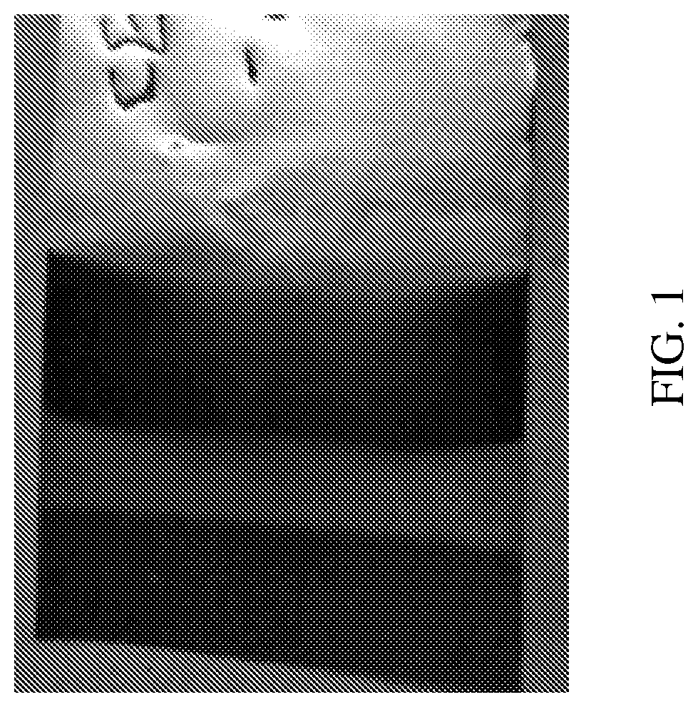
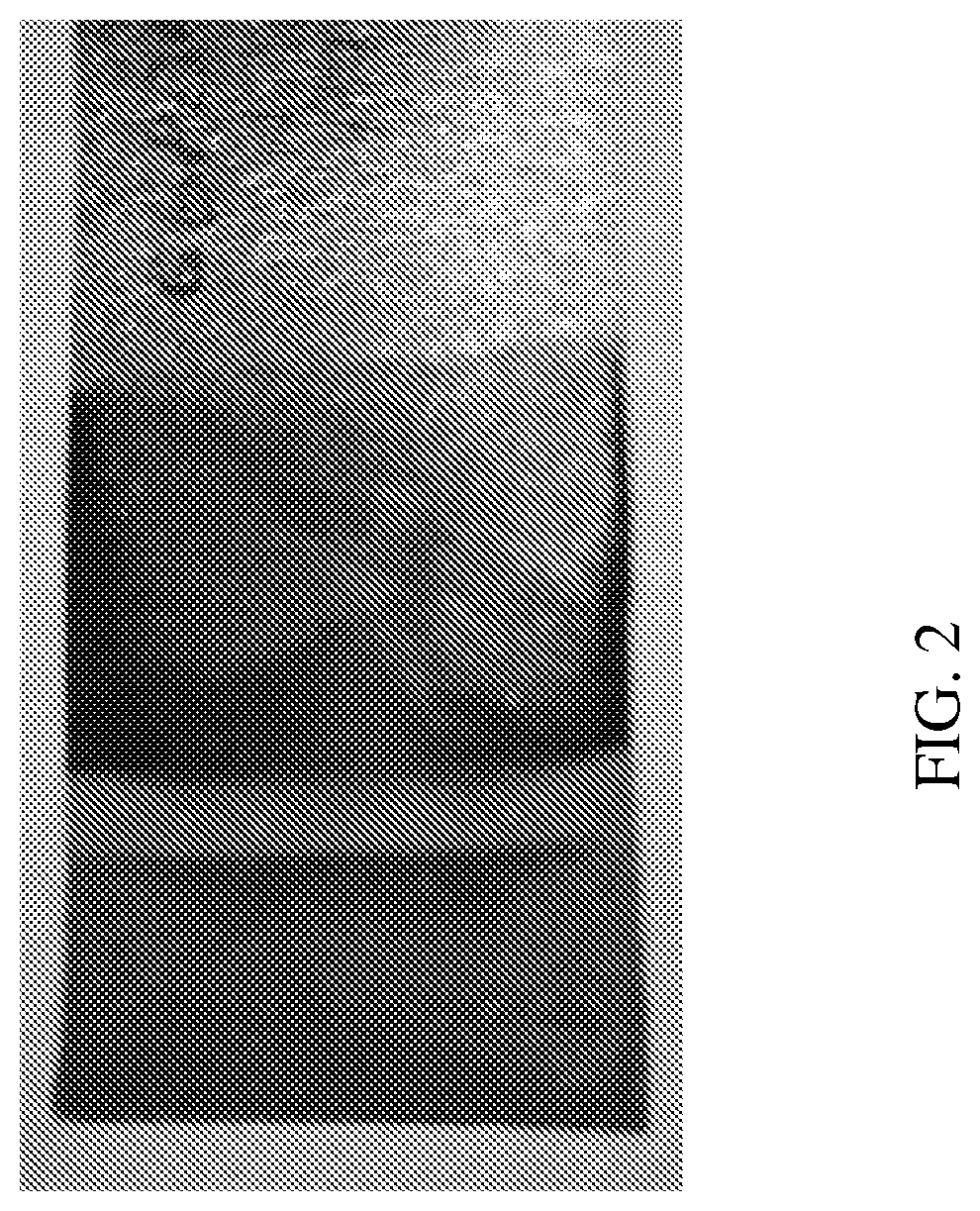
[0180]FIG. 1 shows a thin-film battery comprising the packaging element according to Example 1 of the present invention and FIG. 2 shows a thin-film battery comprising the packaging element according to Example 2 of the present invention.

[0181]Deposition of Thin-Film Battery of Examp...

examples 5 and 6

hin-Film Battery Comprising the Packaging Element According to Some Embodiments of the Present Invention (Joining of Layers)

[0185]LiCoO2 cathode layer was prepared by EPD on an aluminum substrate, graphite anode was prepared by EPD or by doctor-blade, and Celgard® (25 μm thick) separator layer was disposed between the anode and cathode layers. Example 5 was prepared on an aluminum substrate and Example 6 was prepared on a conducting fiber composed of 57% polyester, 23% copper and 20% nickel.

[0186]A full cell was assembled by joining the above components (cathode, separator, anode) together.

[0187]A needle was positioned between the layers for impregnating a liquid electrolyte within the separator layer inside the cell.

[0188]Parylene packaging layer was deposited according to the procedure described in Example 1 and Example 2 above.

[0189]Electrolyte Leakage Test:

[0190]Electrolyte comprising 1M LiPF6 Ethylene carbonate and dimethyl carbonate in 1:1 volume ratio, 0.5 ml was inserted thr...

example 7

oretic Deposition of Composite Graphene and Silicon-Graphene Anode from Aqueous Electrophoretic Bath

[0192]Stable graphene colloids modified by oxidation product of p-phenylene diamine (OPPD) is synthesized. Exfoliated graphen oxide (rGO) / graphene oxide (GO) is prepared from natural graphite. The graphitic oxide was prepared by adding powdered flake graphite and of sodium nitrate in the weight ratio of 2:1 into sulfuric acid.

[0193]Potassium permanganate in the weigh ration of 3:1 to graphitic oxide was added to the suspension. After 30 minutes, the suspension was diluted and treated with hydrogen peroxide to reduce the residual permanganate and manganese dioxide to colorless soluble manganese sulfate. The suspension was filtered to collect the graphitic oxide.

[0194]GO in the concentration of 0.5-2 g / l in water is mixed and sonicated with 5-10 g / l of p-phenylene diamine (PPD) dissolved in N,N dimethylformamide (DMF) or Triton X 100 surfactant. The colloid and the solution is mixed and...


PUM

PropertyMeasurementUnit
thicknessaaaaaaaaaa
thicknessaaaaaaaaaa
voltageaaaaaaaaaa

Abstract

Provided is a packaging element including a polymer layer and having a thickness of between 10 and 200 micro meter; wherein the packaging element being for use in providing an essentially sealed, void-free enclosure of an energy storage device, and wherein the polymer is selected from: poly(para-xylylene), poly-m-xylylene adipamide, dielectric polymer, silicone-based polymer, polyurethane, acrylic polymer, rigid gas impermeable polymer, fluorinated polymer, epoxy, polyisocyanate, PET, silicone rubber, silicone elastomer, polyamide and any combinations thereof.

Description

RELATED APPLICATIONS[0001]This application claims the benefit of priority of U.S. Provisional Patent Application Nos. 62 / 441,462 and 62 / 441,463 filed Jan. 2, 2017, the contents of which are incorporated by reference as if fully set forth herein.FIELD AND BACKGROUND OF THE INVENTION[0002]Some embodiments of the present invention relate to energy storage devices and systems, and, more specifically, but not exclusively, to components for energy storage devices and systems, including electrodes, electrolytes and packaging materials.[0003]Energy storage systems can be utilized in a wide range of electronic applications, including computers, mobile devices, personal digital assistants, power tools, navigational and communications equipment, power storage and automotive management systems. The architecture of such systems is generally constructed of a cell composed of layers comprising an anode layer, a cathode layer and a membrane (electrolyte, separator) layer disposed therebetween. For ...

Claims


Application Information

Patent Timeline
Patent Type & Authority Applications(United States)
IPC IPC(8): H01M2/02H01M4/04C25D13/02H01M10/0525H01M4/38H01M4/48H01G11/78H01M50/105H01M50/121H01M50/124H01M50/131H01M50/133
CPCC25D13/02H01M10/0525H01M4/386H01G11/78H01M2/0207H01M4/483H01M2/028H01M4/0457H01M4/131H01M4/133H01M4/134H01M4/1391H01M4/1393H01M4/1395H01M4/485H01M4/587H01M4/661H01M4/663H01M4/667H01M2004/027C25D13/22H01G11/82H01M10/052H01M10/0565H01M10/0569H01M2010/0495H01M10/0585H01M6/40H01M50/1243H01M50/124H01M50/24H01M50/446H01M50/105H01M50/133H01M50/131H01M50/121Y02E60/10Y02P70/50
Inventor SCHREIBER, EREZBURSHTAIN, DORONGAL-OZ, RESHEFLANCUSKI, ANICA
Owner 3DBATTERIES LTD
Why Eureka
Try Eureka