Joint for steel pipe having high galling resistance and surface treatment method thereof

a joint and galling resistance technology, applied in the direction of hose connections, screw threaded joints, mechanical devices, etc., can solve the problems of inability to provide a stable galling resistance, inability to stably provide galling resistance, and inability to repair galling in the threaded joints, etc., to achieve saturated lubricating performance, reduce heating time, and enhance lubricating performance

Inactive Publication Date: 2000-02-22
NSCT PREMIUM TUBULARS
View PDF28 Cites 234 Cited by
  • Summary
  • Abstract
  • Description
  • Claims
  • Application Information

AI Technical Summary

Benefits of technology

In this connection, the heating time may be arbitrarily determined in accordance with the size and shape of the joint of steel pipe. In order to reduce the heating time and prevent the occurrence of dripping of the solid lubricant in the process of baking conducted after the solid lubricant has been coated, the joint of steel pipe may be previously heated before the solid lubricant is coated on the joint of steel pipe.
By the methods explained above, thickness of the solid lubricant coating layer formed on the joint of steel pipe is restricted into a range from 10 to 45 .mu.m. When the coating thickness is smaller than 10 .mu.m, the object of enhancing the lubricating performance of the present invention can not be sufficiently accomplished. When the coating thickness is smaller than 10 .mu.m, there is caused a problem in which the frequency of making up and breaking out of the joint of steel pipe is decreased. On the other hand, when the thickness of the coating layer exceeds 45 .mu.m, the lubricating performance enhancing effect is saturated. Therefore, the thickness of the coating layer exceeding 45 .mu.m is not economical. When the thickness of the coating layer exceeds 45 .mu.m, the adhesion property of the solid lubricant coating layer tends to deteriorate, and the coating layer is peeled off. Accordingly, in the present invention, thickness of the solid lubricant coating layer is restricted into a range from 10 to 45 .mu.m, and it is preferable that the thickness of the solid lubricant coating layer is restricted into a range from 15 to 30 .mu.m.
When the solid lubricant coating layer is formed on the manganese phosphate chemical formation coating layer by the solid lubricant described above, the adhesive property of the solid lubricant coating layer to the manganese phosphate chemical formation coating layer is very high, so that the toughness and hardness of the coating layer can be enhanced, that is, it is possible to provide a coating of high mechanical strength and high lubricating performance. In the present invention, the solid lubricant coating layer is composed of a solid lubricant containing the powder of molybdenum disulfide or tungsten disulfid

Problems solved by technology

Accordingly, galling incapable of being repaired tends to occur in the threaded joint.
Therefore, it is impossible to stably provide a galling resistance.
Therefore, it is impossible to provide a stable galling resistance by the above technique over a long period of time.
As described above, by the metallic surface treatment described in the example, it is impossible to provide a galling resistance under the condition of no lubricant.
According to Japanese Unexamined Patent Publication Nos. 63-210487 and 6-11078, it is disclosed that the performance of grease is deteriorated when high pressure is given to grease coated on a threaded joint in the process of making up the threaded joint, that is

Method used


Image

  • Joint for steel pipe having high galling resistance and surface treatment method thereof
  • Joint for steel pipe having high galling resistance and surface treatment method thereof
  • Joint for steel pipe having high galling resistance and surface treatment method thereof

Examples


example 1

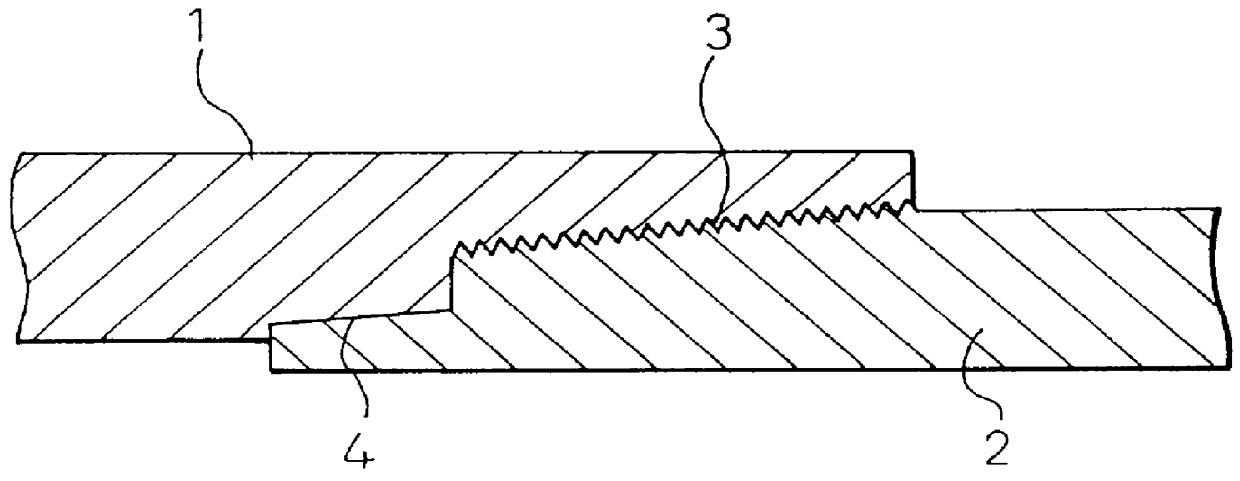
With respect to the box and the pin illustrated in FIG. 1 which are members to compose a joint of steel pipe, the respective screw portions and metal-metal contact portions were subjected to the treatment described as follows. As a surface preparation, on the contact boundary surface of the box, there was provided a manganese phosphate chemical formation coating layer, or there were provided a surface preparation nitriding layer and a manganese phosphate chemical formation coating layer. Alternatively, there was provided a surface preparation nitriding layer, and the thus provided surface preparation nitriding layer was subjected to sand blasting. Concerning the resin coating, there were provided a resin coating layer of molybdenum disulfide and polyamideimide resin, a resin coating layer of molybdenum disulfide and epoxy resin, and a resin coating layer of molybdenum disulfide and furan resin, wherein the ratios of composition were set at predetermined values. The thus provided sol...

example 2

An evaluation of the joint was made as follows. Concerning the joint of a steel pipe, that is, concerning the box (joint member) 1 and the pin (end portion of a steel pipe) 2, the respective thread portions 3 and the metal-metal sealing portions 4 were coated with the manganese phosphate chemical formation coating layer, or the surface preparation nitriding and the manganese phosphate chemical formation coating layer, and the solid lubricant coating layer according to the present invention. The thus produced joints were subjected to the evaluation test.

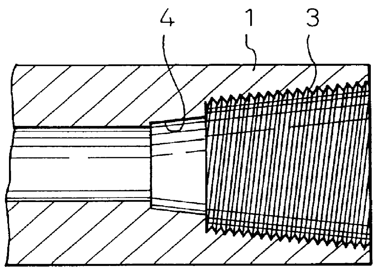
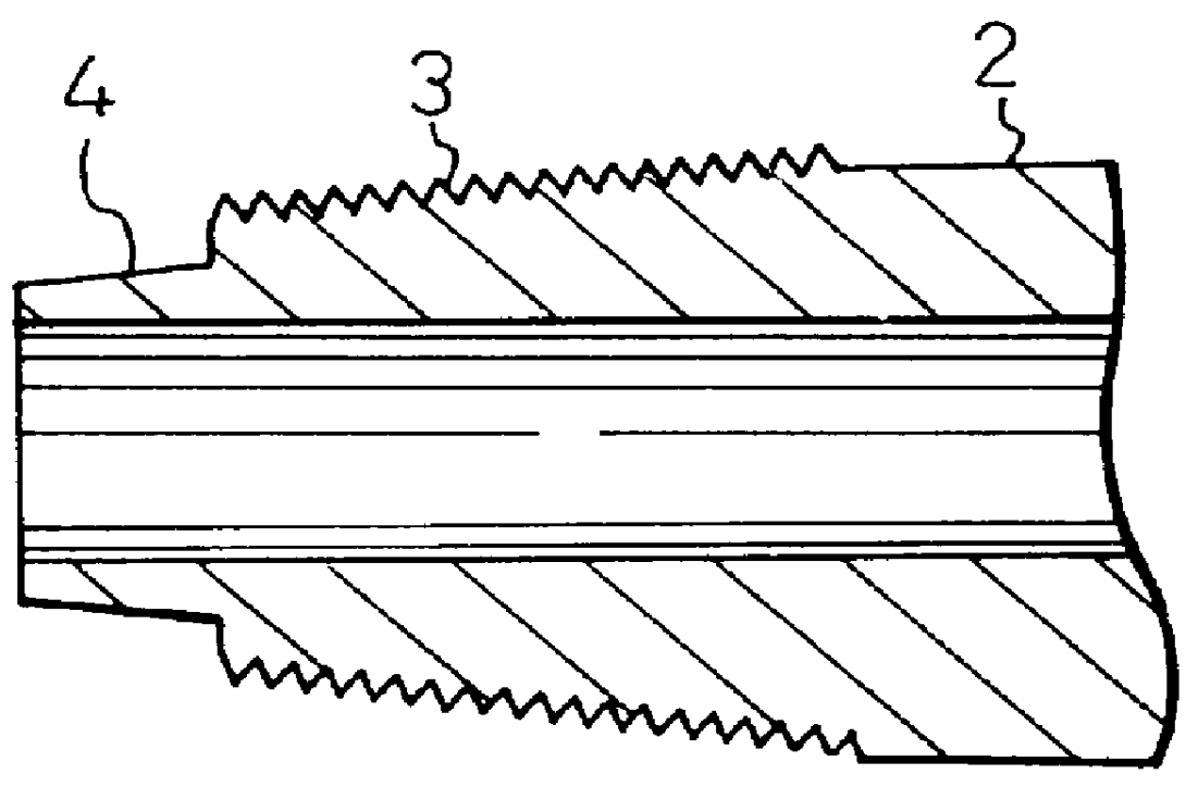
As illustrated in FIG. 2, the thus produced box 1 and the pin 2 to be evaluated were engaged with each other. Next, the box 1 and the pin 2 were made up by a fastening machine while a predetermined intensity of torque was given in accordance with the experiment condition. The box 1 and the pin 2 were slid on each other while the thread portion 3 and metal-metal sealing portion 4 were given a high surface pressure. After that, the box ...

example 3

A box 1, the inner diameter of which was 7 inches, made of steel corresponding to N-80 was degreased in a solvent type degreasing agent and washed in water. Then it was subjected to the heating nitriding at 450.degree. C. for 30 minutes in the molten salt bath of (20% NaCN-15% KCN-17.5% NaCNO-17.5% KCNO-10% Na.sub.2 CO.sub.3 -20% K.sub.2 CO.sub.3). After that, the box 1 was cooled in an oil bath. The box 1 which had been subjected to the nitriding in the above manner was degreased in a solvent and cleaned in an aqueous solution of 5% H.sub.2 SO.sub.4 at the room temperature for 5 seconds and then washed in water. After that, the box 1 was subjected to the pretreatment conducted in the bath of (titanium colloid-sodium pyrophosphate) of 0.8 g / l at room temperature for 2 minutes. Then, the box 1 was treated in the bath of manganese phosphate chemical formation of (8.7 g / 1Mn.sup.2+ -0.2 g / 1Ni.sup.2+ -0.6 g / 1Fe.sup.2+ -32.3 g / 1PO.sub.4.sup.3- -5.7 g / 1NO.sub.3.sup.- -0.6 g / 1F.sup.-) at 90...


PUM

PropertyMeasurementUnit
Fractionaaaaaaaaaa
Percent by massaaaaaaaaaa

Abstract

PCT No. PCT/JP95/02034 Sec. 371 Date May 23, 1997 Sec. 102(e) Date May 23, 1997 PCT Filed Oct. 4, 1995 PCT Pub. No. WO96/10710 PCT Pub. Date Apr. 11, 1996An object of the present invention is to provide galling resistance to a threaded joint used for an oil well pipe. On a thread portion and a metallic sealing portion of the joint, there is provided a manganese phosphate chemical formation coating layer, or alternatively there are provided a nitriding layer of 1 to 20 mu m thickness and a manganese phosphate chemical formation coating layer of 5 to 30 mu m thickness, and also there is coated a solid lubricant which contains powder of molybdenum disulfide or tungsten disulfide and also contains one of epoxy resin, furan resin and polyamide resin as an essential component, and a ratio of composition is maintained at a specific value, so that a solid lubricant coating layer of 10 to 45 mu m thickness can be formed by heating. Due to the above surface treatment, even when the frequency of repetition of fastening and unfastening of the joint is increased, the occurrence of galling can be prevented over a long period of time.

Description

The present invention relates to a threaded joint, the galling resistance of which is high even when it is used under the condition of no lubricant. More particularly, the present invention relates to a threaded joint used for joining oil well steel pipes when crude oil is mined, and also used for joining steel pipes in a pipeline to transport crude oil after it has been mined, and the galling resistance of the threaded joint is high even when it is used under the condition of no lubricant, that is, under the condition in which no lubricant is coated on the threaded joint which is repeatedly fastened and unfastened. The present invention also relates to a method of surface treatment of the threaded joint of steel pipes.In general, threaded joints are used for the tubing and casing when an oil well is drilled. When these threaded joints are used in an actual environment, they are given a compound force including an internal and external pressure, an axial force and a bending force. A...

Claims


Application Information

Patent Timeline
IPC IPC(8): C23C22/83C23C22/18C23C22/82C23C22/05F16L57/06F16L57/00F16L58/18F16L58/00F16L15/00F16L15/06E21B17/02E21B17/042
CPCC23C22/18C23C22/83F16L15/001F16L57/06F16L58/182F16L15/00E21B17/042Y10T29/49885
Inventor TSURU, EIJIOKA, MASAHARUNAGAYOSHI, HARUYUKINAKASHIMA, AKIRAHIGUCHI, SEIJUNINOUE, RYUSUKEAKIYAMA, TOSHIOSAGARA, KAZUMI
Owner NSCT PREMIUM TUBULARS
Why Eureka
Try Eureka