Method for manufacturing fibril system fiber

a technology of fibril system fiber and manufacturing method, which is applied in the direction of filament/thread forming, manufacturing tools, lignocellulosic moulding material treatment, etc., can solve the problems of insufficient control of the shape of the fibrillated fiber structure, limited composition of the fibrillated fiber obtained, and inability to achieve industrial advantages

Inactive Publication Date: 2001-06-19
MITSUBISHI RAYON CO LTD
View PDF54 Cites 28 Cited by
  • Summary
  • Abstract
  • Description
  • Claims
  • Application Information

AI Technical Summary

Benefits of technology

The present invention provides fibril system fibers suitable for uses in filters and artificial leathers, and provides an industrially advantageous manufacturing method for such fibril system fibers. In other words, the present invention provides a manufacturing method which makes manufacturing under low temperature and low pressure conditions possible, and furthermore, is applicable to macromolecular polymers having a comparatively high glass transition temperature, which could not be used in conventional methods, and macromolecular polymers subject to thermal deformation.
When the amount of solution discharged decreases, the fibers become thinner on average, and although fibrillation proceeds, the length of the fibers is shortened. When, on the other hand, the amount of solution discharged is increased, the average diameter of the fibers also increases, and the degree of fibrillation declines.

Problems solved by technology

However, the pulp material obtained by means of such a method is in a fibrillar shape having a plurality of tentacle-shaped projections, the smallest dimension of which does not exceed 10 microns, or is in a thin film shape or a ribbon shape, so that the shape thereof is insufficiently controlled as a fibrillated fiber structure.
This method requires the instantaneous volatilization of the solvent, so that it is necessary to employ a solvent having a comparatively low boiling point, for example, benzene, toluene, cyclohexane, methylene chloride, or the like, and furthermore, it is necessary to select a polymer which forms a uniform solution in the solvent employed under high temperature and high pressure conditions, and which, moreover, is not soluble in this solvent when extruded into a low pressure region, so that the composition of the fibrillated fibers obtained is limited.
Furthermore, this method involves the use of low boiling point solvents, and the maintenance of high pressure and high temperature states, so that it is not industrially advantageous.
Furthermore, the fibers obtained are plexifilaments, and it is difficult to form discontinuous fibrillated fibers using such a method.
However, in this method, it is necessary to employ an extruder having a special structure because the polymer is dispersed in a large amount of water, and this can not be accomplished easily.
However, these methods also involve high-pressure operations.
However, although the pressure is lower in this method, it is still necessary to maintain the emulsion at a pressure within a range of 10-20 atmospheres.
However, the viscosity of the polymer solution which is employed in this method is within a range of from 10 cP to 10.sup.5 cP, and this is low in comparison with the viscosity of polymer solutions employed in the wet spinning of common fibers, so that this method is difficult to use for widely used polymers.
Furthermore, the substances obtained are in pulp form, and are not appropriate for use in non-woven cloths which are employed in filter applications and the like.
However, in this method, it is necessary to pass a high viscosity polymer solution coming out of an extrusion port through a further gap, and blockage of the gap by the polymer solution is likely to occur, so that this method is not industrially advantageous.
However, in this method, a thermally meltable polymer is a prerequisite, so that the method is not appropriate for use with polymers having a high melting temperature or polymers which are thermally deformable.
However, in this method, after the fibers have been produced, it is necessary to elute the island components, and this is not economical.
Furthermore, it is presently difficult to spin minute islands-in-a-sea type fibers using solution spinning, which is a spinning method for macromolecular substances which do not thermally melt.
However, this method is applicable to thermoplastic resins; this method can not be applied to polymers such as cellulose, cellulose acetate, acrylonitrile polymers, and the like, which have a comparatively high melting point, are subject to thermal deformation, and are difficult to place in a molten state.
However, as in the case of the islands-in-a-sea type fiber described above, a polymer must be removed by elution, so that this is not economical, and in consideration of present-day environmental problems, it is necessary to solve the problem of the recovery or disposal of the eluted polymer solution, so that this is not an industrially advantageous method.
However, in this method, even after beating, only a portion becomes fibers having a diameter of 0.5 micrometers or less, and the basic fibers remain, so that such pulp is insufficient for uses such as filters and the like which require a high surface area.
Furthermore, when used for artificial leather and the like, the basic fibers have a deleterious effect on the feel, and this is not desirable.
However, this method requires the use of a special device for the beating, so that it is not broadly applicable.
Furthermore, the method may be applied to cellulose; however, it is difficult to apply the method to cellulose acetate or acrylonitrile system polymers, which are useful macromolecules not subject to thermal melting.

Method used


Image

  • Method for manufacturing fibril system fiber
  • Method for manufacturing fibril system fiber
  • Method for manufacturing fibril system fiber

Examples


embodiment 7

230 g of cellulose diacetate (MBH, produced by Daicel Chemical Industries Ltd.) was dissolved in 770 g of acetone, and a 23 weight percent cellulose diacetate solution in acetone was prepared.

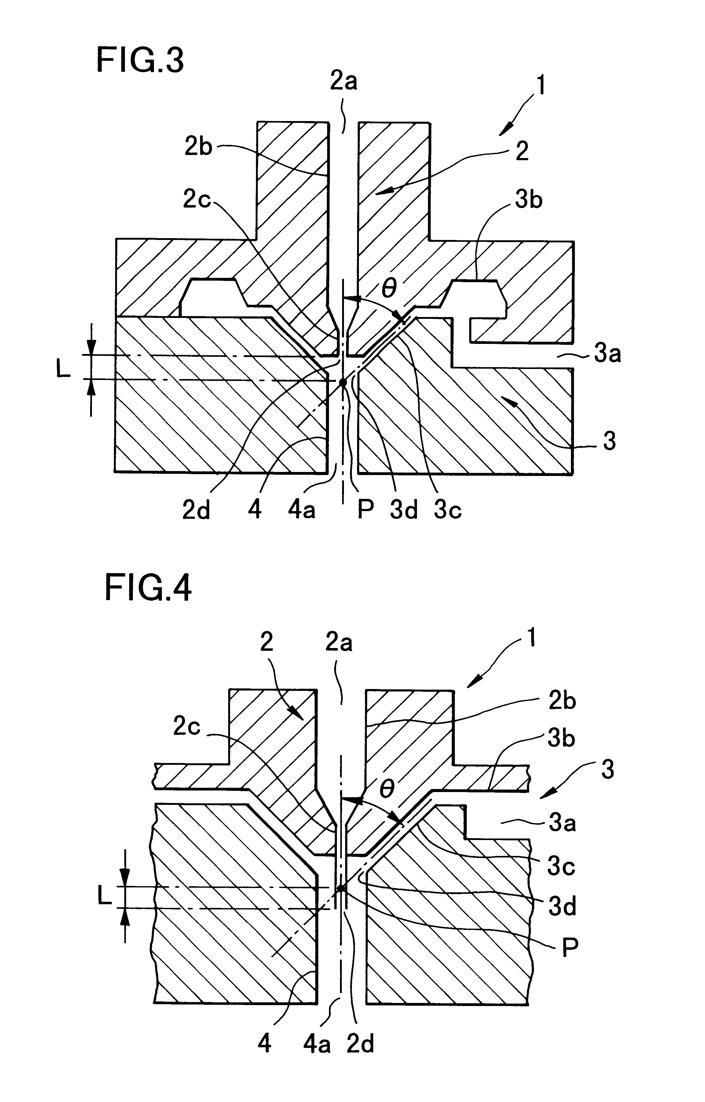
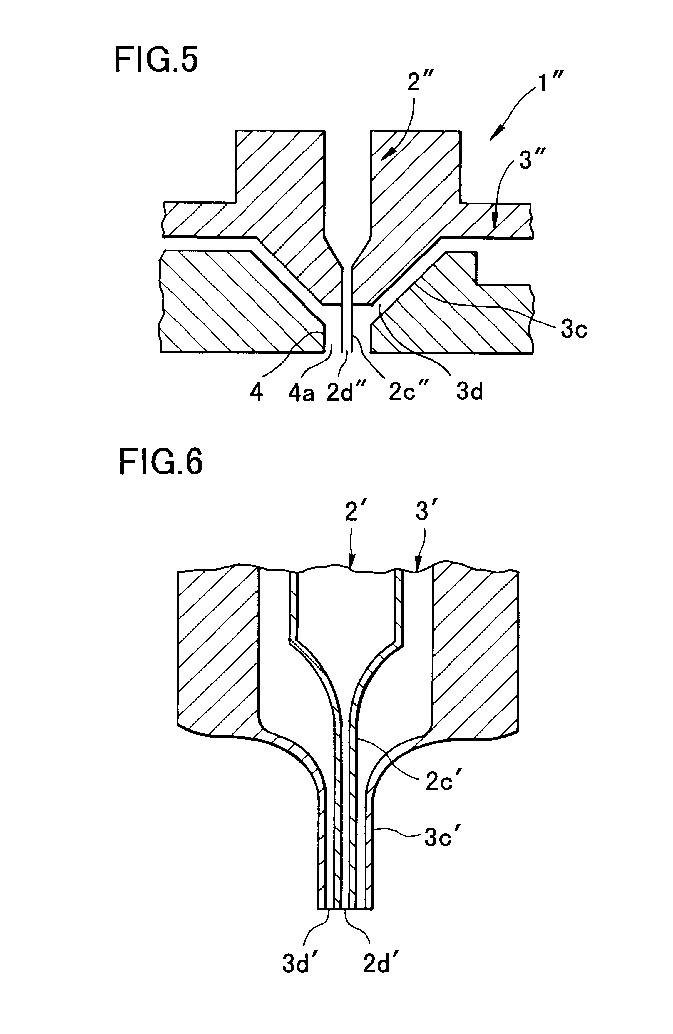
While maintaining the temperature of the solution obtained at 40.degree. C., the solution was extruded under nitrogen pressurization of 1.5 kg / cm.sup.2, and using a gear pump, a standard amount of the solution was supplied to the nozzle part depicted in FIG. 3, while water vapor was simultaneously supplied. The control of the amount of water vapor supplied was conducted by controlling the supply pressure using a reducing pressure valve. The amount of water vapor was measured by injecting only water vapor from the nozzle shown in FIG. 3 into the coagulating liquid, and obtaining the increase in weight per unit time.

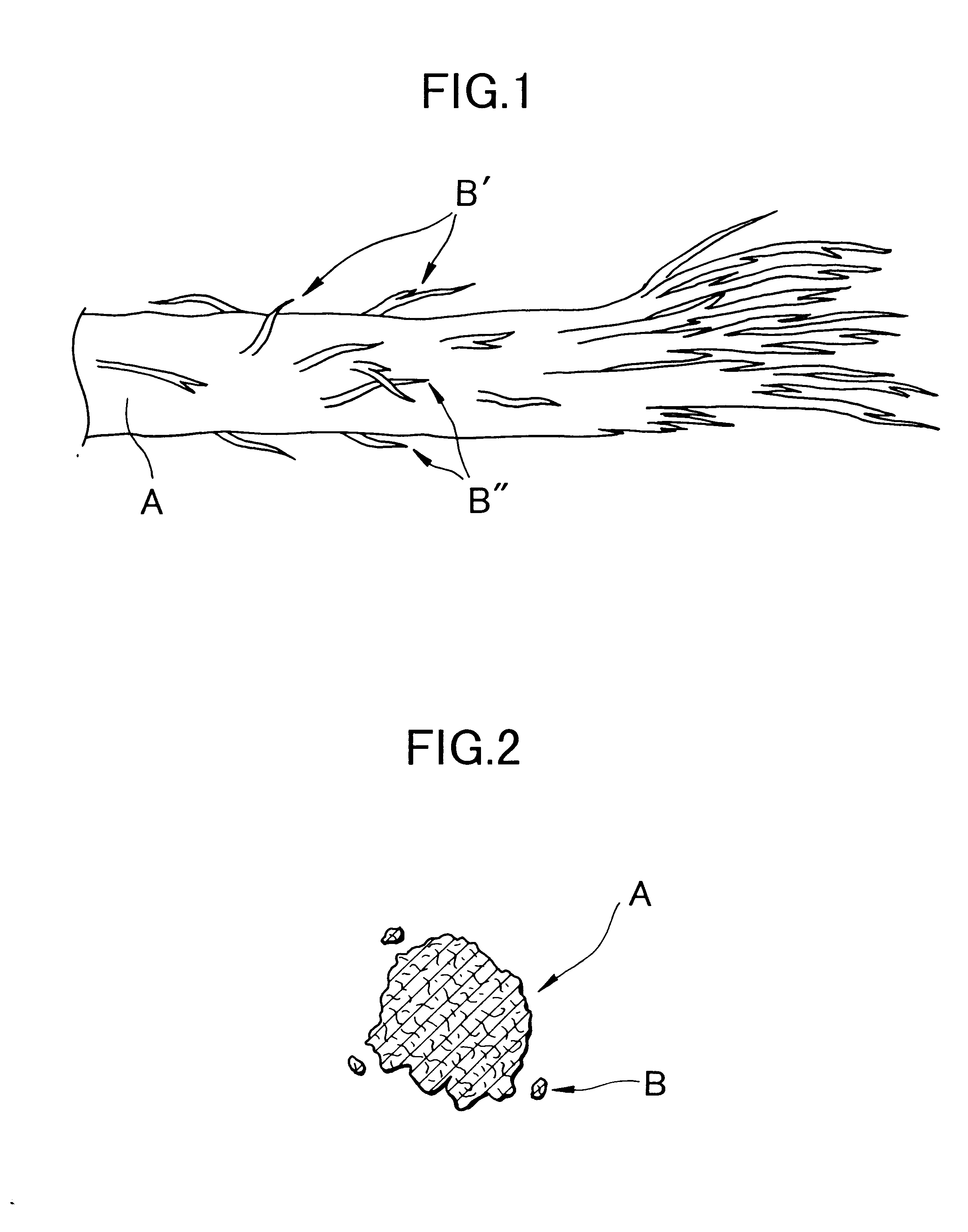
Using a nozzle in which the solution discharge port had a diameter of 0.2 mm.phi., the mixing cell had a diameter of 2 mm.phi. and a length of 1.5 mm and was cylindrical, in which the...

embodiment 8

A 23 weight percent cellulose diacetate solution in acetone was prepared using a method identical to that of embodiment 7. Formation of the cellulose diacetate was conducted using a method identical to that of embodiment 7, with the exception that the discharge rate of the cellulose diacetate solution was changed to 6 ml / min.

A coagulum having a form identical to that of the coagulum obtained in embodiment 7 was obtained, and the specific surface area of the coagulum was 10.5 m.sup.2.

embodiment 9

A 23 weight percent solution of cellulose diacetate in acetone was prepared by a method identical to that of embodiment 7. Formation of the cellulose diacetate was conducted by a method identical to that of embodiment 7, with the exception that extrusion was conducted from the mixing cell output into a coagulating bath comprising a 30 weight percent solution of acetone in water, at a temperature of 30.degree. C., and a coagulum having a specific surface area of 10.0 m.sup.2 / g was obtained.


PUM

PropertyMeasurementUnit
angleaaaaaaaaaa
angleaaaaaaaaaa
pressureaaaaaaaaaa

Abstract

The present invention provides fibril system fibers which may be employed in filter applications and in artificial leather applications, and also provides an industrially superior manufacturing method for such fibril system fibers, and a spinning nozzle. The fibril fibers of the present invention include at least one macromolecular polymer having a film forming ability, and they have a structure in which fibrillated fibers having a diameter of 10 micrometers or less branch from main fibers having a width within a range of 0.1 micrometers-500 micrometers, and a length within a range of 10 micrometers-10 cm.

Description

This is a Continuation of International Appln. No. PCT / JP97 / 00654 filed Mar. 4,1997 which designated the U.S.The present invention relates to discontinuous fibrillated fibers from a polymer solution in which macromolecular polymers having a film forming capacity are dissolved in a solvent, to surface-fibrillated fibers, and to split fibers containing fibrils and fibril fibers comprising such fibers. Furthermore, the present invention relates to a manufacturing method for fibril fibers and to a spinning nozzle which is preferentially employed in the manufacture thereof.Discontinuous fibrillated fibers are preferentially employed as a raw material for obtaining threads or sheet-form material such as non-woven cloth or the like: such fibers are represented by pulp. Recently, in fields requiring a high filtration ability with low pressure loss, such as air filters and the like, the effective use of extremely thin fibers having a large surface area has been required. The use of fibrillat...

Claims


Application Information

Patent Timeline
Patent Type & Authority Patents(United States)
IPC IPC(8): D01D5/00D01D5/40D01F2/28D01F6/18
CPCD01D5/40
Inventor HOSAKO, YOSHIHIKOYAMADA, TERUYUKISHINADA, KATSUHIKOHABARA, HIDEAKIOGAWA, SHIGEKINAGAMINE, SADATOSHIHIROTA, KEIJIKOZAKURA, TAKASHI
Owner MITSUBISHI RAYON CO LTD
Why Eureka
Try Eureka