Method of manufacturing an electric heating element

a manufacturing method and heating element technology, applied in the direction of heating element shapes, ohmic resistance heating, hot plate heating arrangements, etc., can solve the problems of low adhesion strength of electric heating circuit, and affecting the uniformity of temperature distribution

Inactive Publication Date: 2002-11-26
TATEHO CHEM IND CO
View PDF16 Cites 31 Cited by
  • Summary
  • Abstract
  • Description
  • Claims
  • Application Information

AI Technical Summary

Problems solved by technology

(1) This type is limited to the type wherein the circuit pattern is baked only on one side of the ceramic substrate (single-side baking) . Because the surface with the circuit formed thereon is exposed, it is necessary to insulate this portion depending on the application.
(2) Adhesion strength of the electric-heating circuit is low and tends to peel off.
(3) Maximum operating temperature is limited to the melting point of glass used as the binder, with the operating temperatures 400 to 500 C. at most, and operation at a high temperatures above 1000 C. is prohibited.
(2) A heater made by integrally baking an electric-heating circuit at the same time when the ceramic substrate is sintered.
(1) Because the circuit must be covered by the ceramic, the circuit cannot be formed near the peripheral edge of the element, resulting in lower temperatures near the edges. Thus, it is difficult to achieve uniform temperature distribution.
(2) This type of thin planar shape is subject to a warp during sintering. Pressurized sintering is required to obtain a heater element without warp.
This method essentially involves the problem of deformation taking place during sintering of the ceramic material, and it is difficult to obtain a large-sized sintered article without deformation.
This method requires it to use a die, leading to extremely high costs when producing articles in a small lot.
(3) Electric-heating metals are limited to high melting point metals such as tungsten and molybdenum, which do not melt at the sintering temperature of the ceramic.
Tungsten and molybdenum have a drawback of tendency to oxidize, and the ceramic material that encloses the electric-heating circuit is required to be free of defects and completely air-tight.
It is difficult to use in the air atmosphere at a high temperature over a long period of time.
Tungsten and molybdenum have another problem that the electric resistance and heat generation density of these metals are low.
The ceramic heater has such problems as described above.
Largest drawback of the silicide heat-generating material is that it is very brittle.
However, use of glass as a binder gives rise to a problem with regard to the heat resistance.
Also silicide itself has an intrinsic problem of softening at high temperatures, causing the heater element to deform and droop.
The present situation is as described above, which does not mean that the importance of temperature control is not recognized, but because there is no method available for controlling the temperature economically at a desired rate.
Although precise temperature control is possible in a laboratory without economical considerations in terms of productivity, there is no method of quick and precise temperature control applicable to production lines, capable of quickly setting an optimum temperature for individual film material to be processed without decreasing the productivity.
In order to quickly attain the desired vacuum degree, the object may be heated but there is no method of quickly heating only the object.
In the double-side fusing type, such a problem can occur that molten metal penetrates into a space between the circuit, resulting in short-circuiting.
In a structure wherein the heater circuit is interposed between two ceramic substrates as shown in FIG. 6 and FIG. 7, there is a possibility of the fused metal penetrating laterally to cause short-circuiting.
The thicker the metal film, the higher the possibility of short-circuiting to occur.
Existence of the gap may allow foreign matter to enter, thus resulting in short-circuiting depending on the application.
Simple Si material of (4) has too high electric resistance and is not suitable as an electric-heating alloy.
In the actual treatment, transition periods during which the temperature changes from low to high and high to low levels are loss time of which increase results in a decrease in the productivity.
Reversing the order of coupling increases the loss time during heating and results in significant decrease in the productivity.

Method used


Image

  • Method of manufacturing an electric heating element
  • Method of manufacturing an electric heating element
  • Method of manufacturing an electric heating element

Examples


example 1

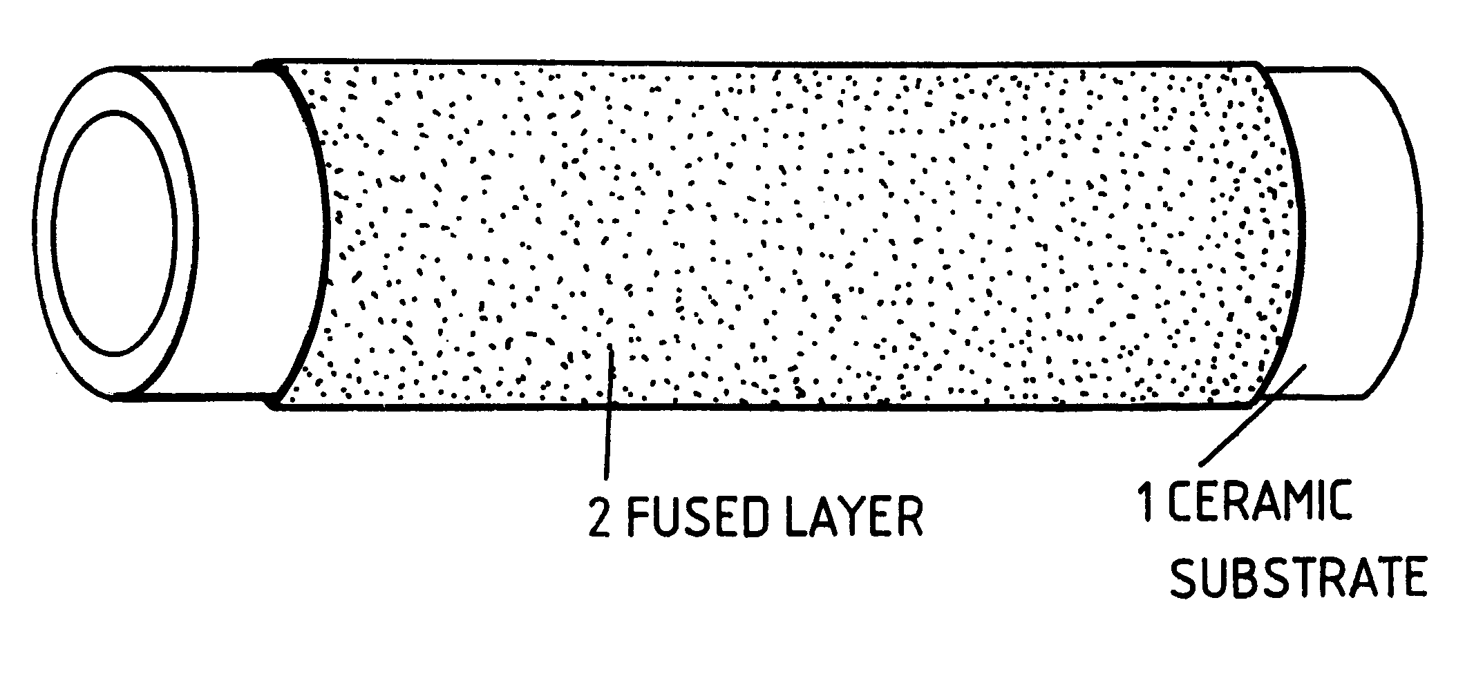
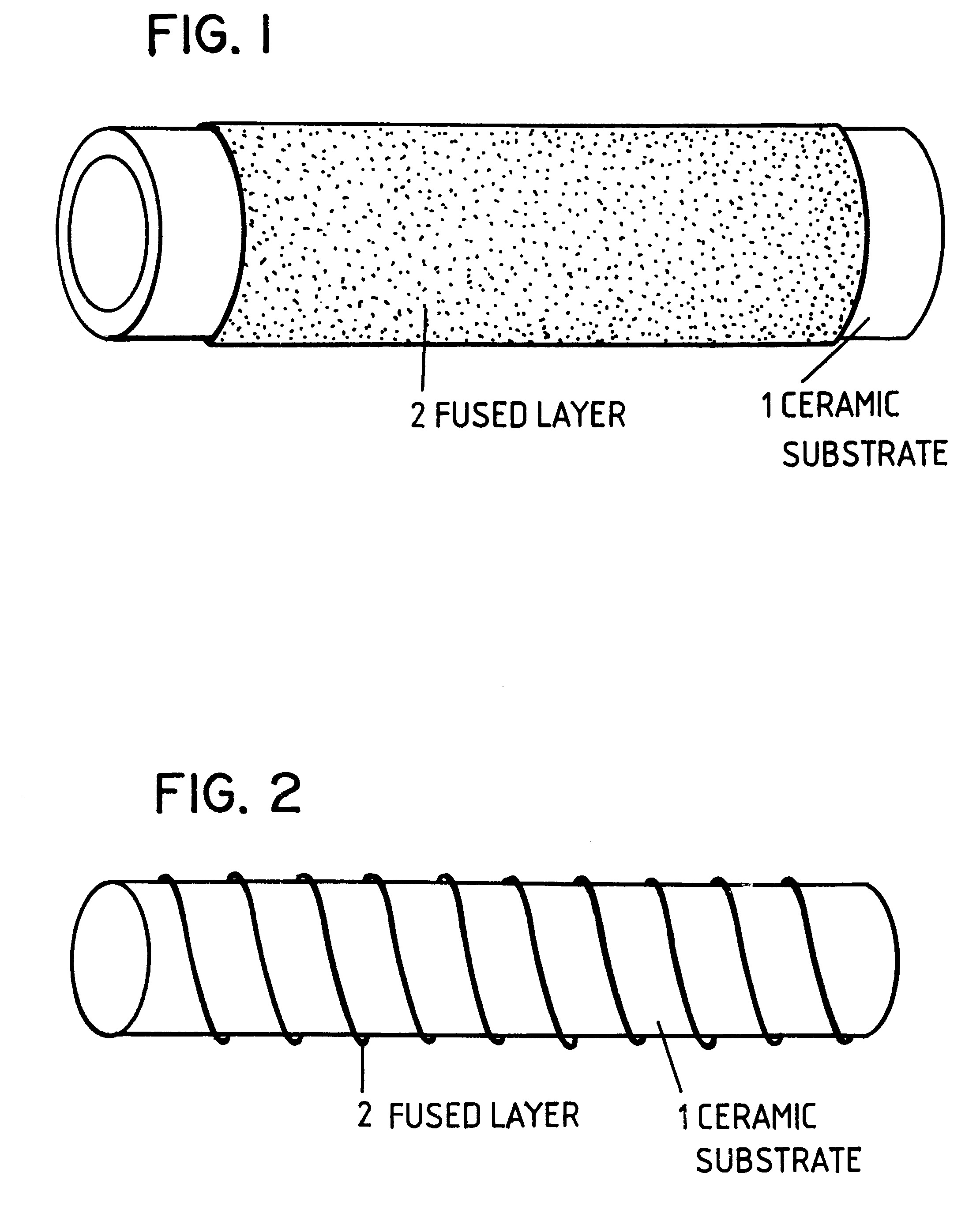
Double-side Fusing Type

Ceramic substrate: Four materials of aluminum nitride, silicon nitride, silicon carbide and alumina are used. The silicon carbide has an electrical resistance of 10.sup.11 ohm.multidot.cm.

Substrate dimension: A plate of 10.times.30.times.0.6 mm

Fused metal: The above-mentioned substrate made of aluminum nitride, silicon nitride, silicon carbide or alumina is coated with a paste of metallic powder having the following composition (shown in Table 1) mixed with ethanol solution of polyvinyl alcohol, in an area 2 mm wide and 22 mm long as shown in FIG. 13. This is laminated with a ceramic substrate having holes (1 mm in diameter) on both ends as shown in FIG. 14, with the assembly being dried and then heated to melt and fuse as shown in FIG. 15. The holes are separated 20 mm apart.

As the Si material, powder made by grinding a semiconductor substrate and powder of 99.999% purity (Al, Mg, Ca, Na<=1 ppm) were used. The powder made by grinding a semiconductor substrate...

example 2

Heating Test

The sample of Example 1 was heat-tested with an alternate voltage applied. A cycle of heating up to 500 C. in five minutes and then leaving to cool down to the normal temperature was repeated 100 times. None of the samples showed peel-off or crack of the heater.

Then oxidation resistance of the fused metal was tested. The sample of Example 1 was heated at 1000 C. for five hours. No change in electrical resistance due to oxidation of the fused film was observed.

example 3

Comparison of Films for Uniform Fusibility

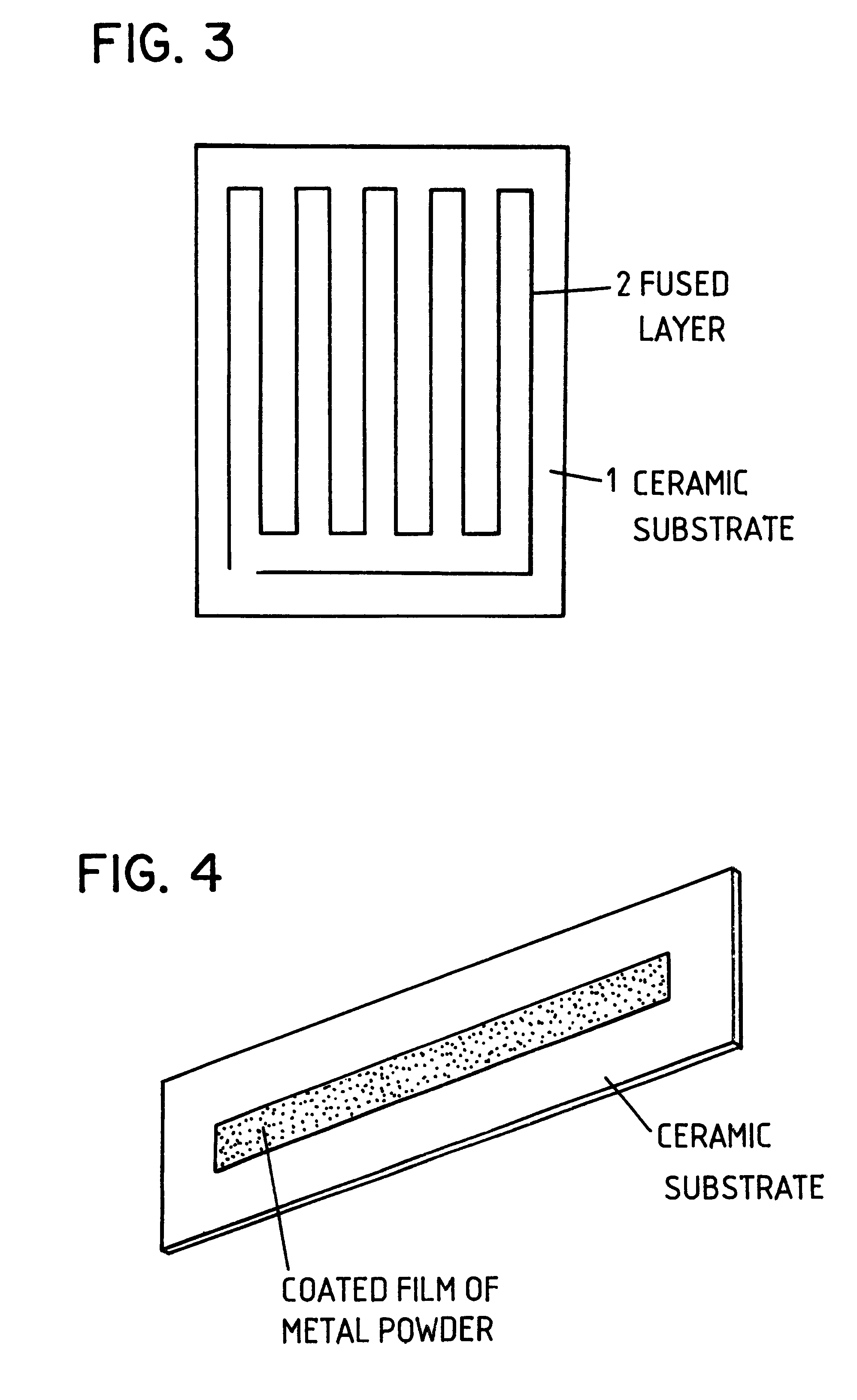
A heater having a heater circuit fused to one side of a ceramic substrate (single-side fused structure) and a heater having a heater circuit fused to two ceramic substrates interposing the heater circuit (double-side fused structure) were compared for uniformity of thickness (convexo-concave, flatness), uniformity of width and surface property.

Ceramic substrate: Aluminum nitride substrate measuring 100.times.100.times.0.6 mm

Fused metal: Two components having different levels of wettability for the fused metal. High-purity Si (99.999%) and Si-25% Ti were selected and compared.

Si powder (particle size under 325-mesh) mixed with ethanol solution of polyvinyl alcohol into a paste was printed to the surface of the aluminum nitride substrate in a circuit pattern shown in FIG. 16. Width of the circuit was 10 mm and space between adjacent circuits was 5 mm.

The single-side fused sample with the circuit printed on one side thereof was dried, and then ...


PUM

PropertyMeasurementUnit
electrical resistanceaaaaaaaaaa
diameteraaaaaaaaaa
purityaaaaaaaaaa

Abstract

In order to eliminate the drawback of an electric heating element formed on an insulating ceramic substrate so that the element is brittle and becomes soft at a high temperature, an electrically heat-generating material film having a microstructure composed of a silicide alone, a mixture of silicide and Si, or Si alone is fused to the surface of a nitride or carbide ceramic insulating substrate.In order to provide an electrostatic chuck by which the temperature of an electrostatically chucked object to be treated, such as a semiconductor substrate, is quickly and precisely controlled, a heating mechanism is coupled with the bottom face of an electrostatically chucking mechanism provided with a dielectric ceramic and electrodes formed on the bottom face of the ceramic, and a cooling mechanism is coupled with the bottom face of the heating mechanism. The heating mechanism has a fusable electric-heating material film between two ceramic insulating substrates having the same or nearly the same coefficients of thermal expansion. The films is fused to the substrates.

Description

The present invention relates to an electric heating element and, more particularly, to an electric heating element having a structure comprising a ceramic insulating substrate and an electrically heat-generating material film, said film being fused to the surface of said electric insulating ceramic substrate.The present invention also relates to a structure of an electrostatic chuck and, more particularly, to a structure of an electrostatic chuck capable of quickly and precisely controlling the temperature of an electrically chucked material to be treated, such as a semiconductor substrate.TECHNICAL BACKGROUNDIn the field of electric heating elements, it is known that a planar heating element having less temperature variation can be obtained by forming a heater circuit on a ceramic plate having high thermal conductivity. Such a heater, referred to as a ceramic heater, is required to have the following characteristics.(1) High adhesion strength between the circuit and the ceramic ma...

Claims


Application Information

Patent Timeline
Patent Type & Authority Patents(United States)
IPC IPC(8): H05B3/28H05B3/14H05B3/22H05B3/20
CPCH05B3/143H05B3/283H05B3/148Y10T29/49082H05B3/20
Inventor MIYATA, SEIICHIRO
Owner TATEHO CHEM IND CO
Why Eureka
Try Eureka