Induction plasma reactor

a plasma reactor and inductive technology, applied in nuclear reactors, electric/magnetic/electromagnetic heating, manufacturing tools, etc., can solve the problems of plasma contamination, high undesirable, and metal contamination source, and achieve high plasma density, high productivity applications, and efficient breakdown of feed gasses

Inactive Publication Date: 2005-02-15
BRAILOVE ADAM ALEXANDER
View PDF8 Cites 61 Cited by
  • Summary
  • Abstract
  • Description
  • Claims
  • Application Information

AI Technical Summary

Benefits of technology

a) High plasma density, leading to the efficient breakdown of feed gasses, and therefore high productivity applications.
b) Low plasma potential and low sheath voltages, minimizing contamination of the plasma by chamber wall material and minimizing erosion of the plasma chamber walls.
c) A relatively low cost and compact means of delivering power to the plasma comprising an AC switching power supply, closely coupled to the plasma.
d) A plasma

Problems solved by technology

Although erosion is desired for some applications such as welding, in many fine processes, such as semiconductor processing, electrode erosion represents a source of metals contamination and is highly undesirable.
Not only can this produce plasma contamination and a gradual erosion of the chamber walls, but it also represents a significant source of power loss for the plasma.
High plasma potentials and high sheath voltages are undesirable.
The overall cost, complexity and size of such a system is relatively large compared to an inductive system, due to the microwave power supply, a microwave tuner, DC magnetic field coils and their associated DC power supplies.
These drawbacks often preclude the use of resonant excitation in many applications.
First, although the problem of erosion and contamination caused by the high voltage sheath is reduced when compared to a capacitive or DC discharge, it is not completely eliminated.
Higher plasma currents result in higher plasma densities, therefore, based on the well known electrical behavior of transformers, it seems advantageous to increase the number of primary turns, N. Unfortunately, this strategy leads to higher voltages across the primary coil of the plasma transformer.
These high voltages, especially near the ends of the primary coil, couple capacitively to the plasma and produce high energy ion bombardment of the walls resulting in sputter contamination, wall erosion, and energy loss in these areas.
In practice, however, the oscillating magnetic flux induces eddy currents in the shield, thereby absorbing part of the applied power.
Another problem with inductive heating is the need for a tube, chamber wall, or window made of dielectric material.
Ceramics and glasses are brittle materials that are sensitive to thermal shock or slight mechanical imperfections.
They can shatter explosively under vacuum pressure.
The use of these brittle chamber materials with toxic gasses poses a risk of sudden uncontrolled release.
Unfortunately, most dielectric materials have poor thermal conductivity.
The difficulty

Method used


Image

  • Induction plasma reactor
  • Induction plasma reactor
  • Induction plasma reactor

Examples


Embodiment Construction

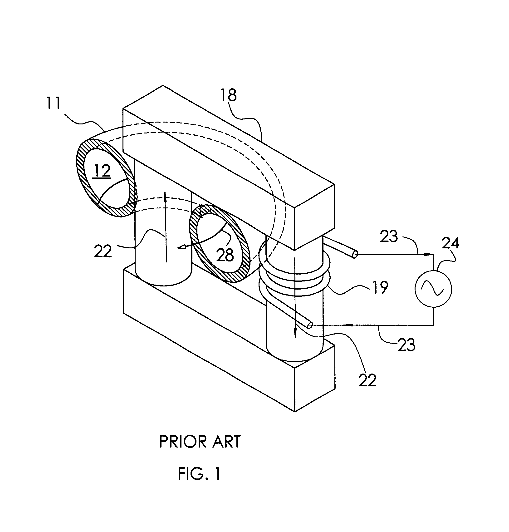
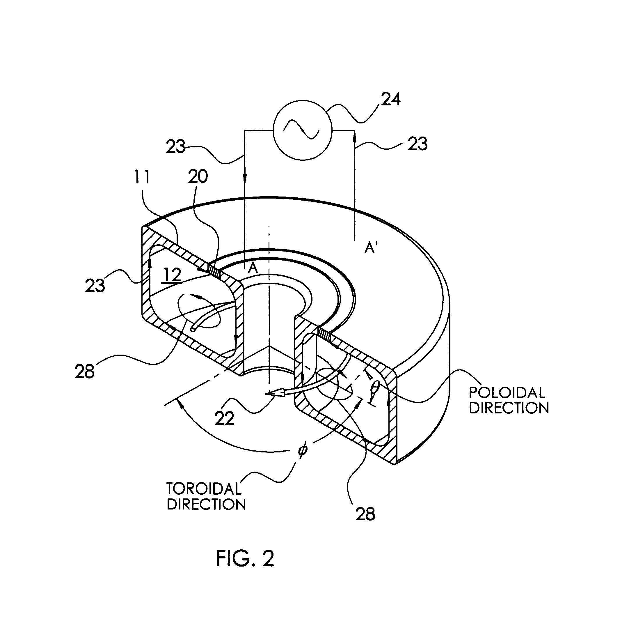
FIG. 1 is a partially sectioned isometric view which illustrates conceptually the prior art of H. U. Eckert (IEEE Transactions on Plasma Science, Vol. PS-2, 1974) as well as patents U.S. Pat. No. 4,431,898, Japan 02-260399, U.S. Pat. No. 5,290,382 and U.S. Pat. No. 6,150,628. The toroidal plasma chamber wall 11 is shown sectioned along a centerline to expose the inside. The toroidal plasma chamber 12 refers to the void that is bounded and defined by the chamber wall 11. The plasma chamber 12 is filled with a working gas at some controllable pressure as well as with the plasma itself. The gas and plasma are not separately illustrated or numbered since they coincide with the plasma chamber 12. An optional gas inlet and outlet, which are not shown in this figure, allow the working gas to flow through the chamber.

Plasma transformer magnetic core 18 forms a closed magnetic path that penetrates through the center hole of the toroidal plasma chamber 12 and encircles a portion of the plasma...


PUM

PropertyMeasurementUnit
Dielectric polarization enthalpyaaaaaaaaaa
Poweraaaaaaaaaa
Densityaaaaaaaaaa

Abstract

The invention is a plasma-generating device useful in a wide variety of industrial processes. The plasma is formed in a chamber having a toroidal topology, and is heated inductively. As with all inductive plasmas, a primary coil carries an applied AC current, which, in turn, generates a corresponding applied AC magnetic flux inside the plasma. This flux induces current to flow through the plasma in closed paths that encircle the flux, thereby heating and maintaining the plasma. In this invention, the applied AC current flows through the primary coil around substantially the short poloidal direction on the torus. Accordingly, the applied magnetic flux is caused to circulate through the plasma along the larger toroidal direction. Finally, the current induced within the plasma will flow in the poloidal direction, anti-parallel to the applied primary current. The plasma chamber wall is preferably made of metal such as aluminum and includes one or more electrical breaks that extend fully around the chamber wall in the toroidal direction. This prevents poloidal currents from being induced in the chamber wall, ensuring effective power transfer to the plasma. Elastomeric seals made from electrically insulating material seal the breaks.

Description

FEDERALLY SPONSORED RESEARCHNot applicableSEQUENCE LISTING OR PROGRAMNot applicableBACKGROUND OF THE INVENTIONThis invention relates to an apparatus for inductively generating plasma. It relates specifically to a robust and low-cost apparatus for producing a compact volume of high-density plasma. More broadly, this invention relates to methods for performing a variety of useful industrial process such as generating reactive gasses, processing semiconductors, destroying gaseous toxic waste, forming nano-particles, and enhancing gaseous chemical processes using the novel apparatus described herein.Gaseous plasma discharges are widely applied in numerous industrial and technological processes. In particular, plasmas are used in many semiconductor manufacturing processes, as well as welding, plasma spraying of materials, nano-particle generation and ion sources. In addition to thermal processes like plasma-spraying and welding, a plasma is an efficient means of enhancing chemical reacti...

Claims


Application Information

Patent Timeline
IPC IPC(8): H05H1/24H05H1/46H05B6/10
CPCH05B6/108H05H1/46H05H1/24H05H1/4652
Inventor BRAILOVE, ADAM ALEXANDER
Owner BRAILOVE ADAM ALEXANDER
Why Eureka
Try Eureka