Method for producing polymer-particle composites

a technology of composites and polymer particles, applied in the direction of diffusing elements, optical elements, instruments, etc., can solve the problems of inability to control the thickness of films, long production time, and requirement of cell or sealing

Inactive Publication Date: 2005-04-19
3M INNOVATIVE PROPERTIES CO +1
View PDF6 Cites 52 Cited by
  • Summary
  • Abstract
  • Description
  • Claims
  • Application Information

AI Technical Summary

Benefits of technology

[0049]Such a polymer-particle composite having a particle packed uniformly therein described above allows even a particle having an extremely small mean particle size, which could not conventionally been dispersed uniformly without aggregation, to be packed uniformly at a high density in a polymeric material, and can also be imparted with a self-standing ability through adjusting a thickness of the polymer-particle composite, whereby providing a wide range of application where the characteristic of the particle are utilized.
[0050]Each step in a method for producing a polymer-particle composite according to the invention is detailed below.
[0051]The first step of the invention, i.e., a step of forming a polymer-containing layer consisting mainly of a polymeric material is described below.
[0052]In the present invention, a method for forming a polymer-containing layer is not particularly limited, and may be a method for forming a sheet alone using an extruder or for forming a layer on a substrate. It is preferred to form a layer on a substrate since a polymer-containing layer in the form of a thin film is useful in most of the cases. A method for forming such a polymer-containing layer on a substrate may employ for example various coating processes such as a spin coating, a screen coating, a roll coating, a dip coating, a die coating and the like. The curing the polymer-containing layer on a substrate may vary depending on the material to be employed, and the solvent may be removed when a polymeric material is present as being dissolved in a solvent, or a thermosetting may be employed when a layer is formed by a reaction on the substrate, or, a irradiation with an actinic ray, such as a light, may also be employed.
[0053]A polymer-containing layer may be formed as a pattern on a substrate if necessary. A method for forming a pattern may for example be a direct print

Problems solved by technology

However, any of the methods described above involves a problematic disadvantage, such as a prolonged production time, a difficulty or an impossibility experienced in controlling the film thickness, the requirement of a cell or a sealing, the lack of self-standing ability, and the like.
While a method in which

Method used


Image

  • Method for producing polymer-particle composites
  • Method for producing polymer-particle composites
  • Method for producing polymer-particle composites

Examples


example 1

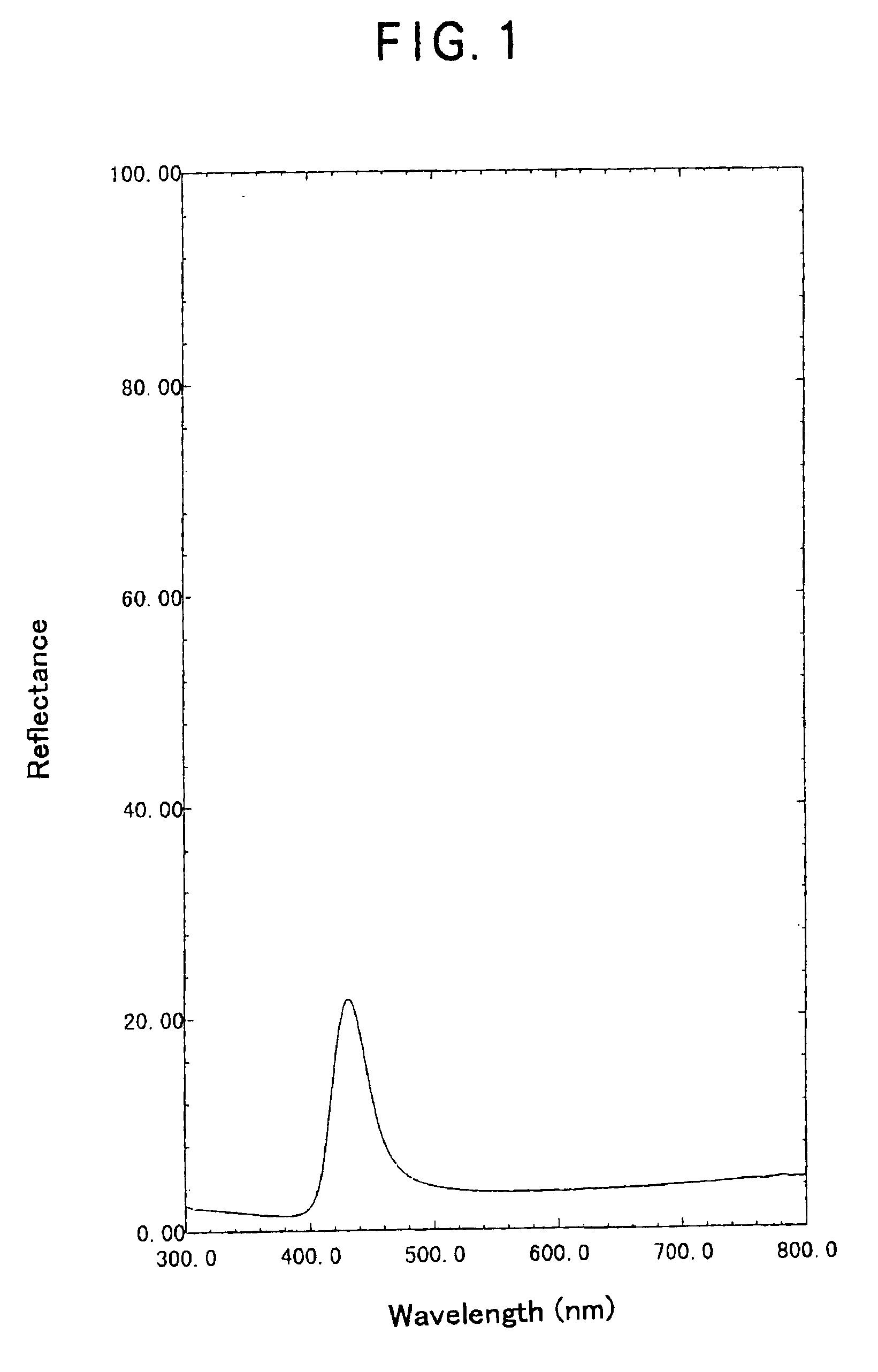
[0119]A glass substrate was spin-coated with a 5% by weight aqueous solution of polydiallyldimethylammonium chloride (Aldrich). After drying at 80° C. for 30 minutes, this coated glass substrate was immersed in a colloidal silica suspension whose particle size was 180 nm (SiO2 concentration: 40% by weight, Nissan Chemical Industries, Ltd) to obtain a silica particle-polydiallyldimethylammonium chloride composite film within several seconds. A part of the polymeric diallyldimehylammonium chloride was considered to undergo a counter ion exchange with —O−Na+on the surface of the silica particle whereby forming an ionic bond, as shown below.

[0120]The reflection spectrum (incidence: 5°) of the silica particle-polydiallyldimethylammonium chloride composite after drying for a day at room temperature is shown in FIG. 1. A peak indicating that the silica particle was packed in the composite film periodically (peak wavelength: 431.5 nm) was observed clearly.

example 2

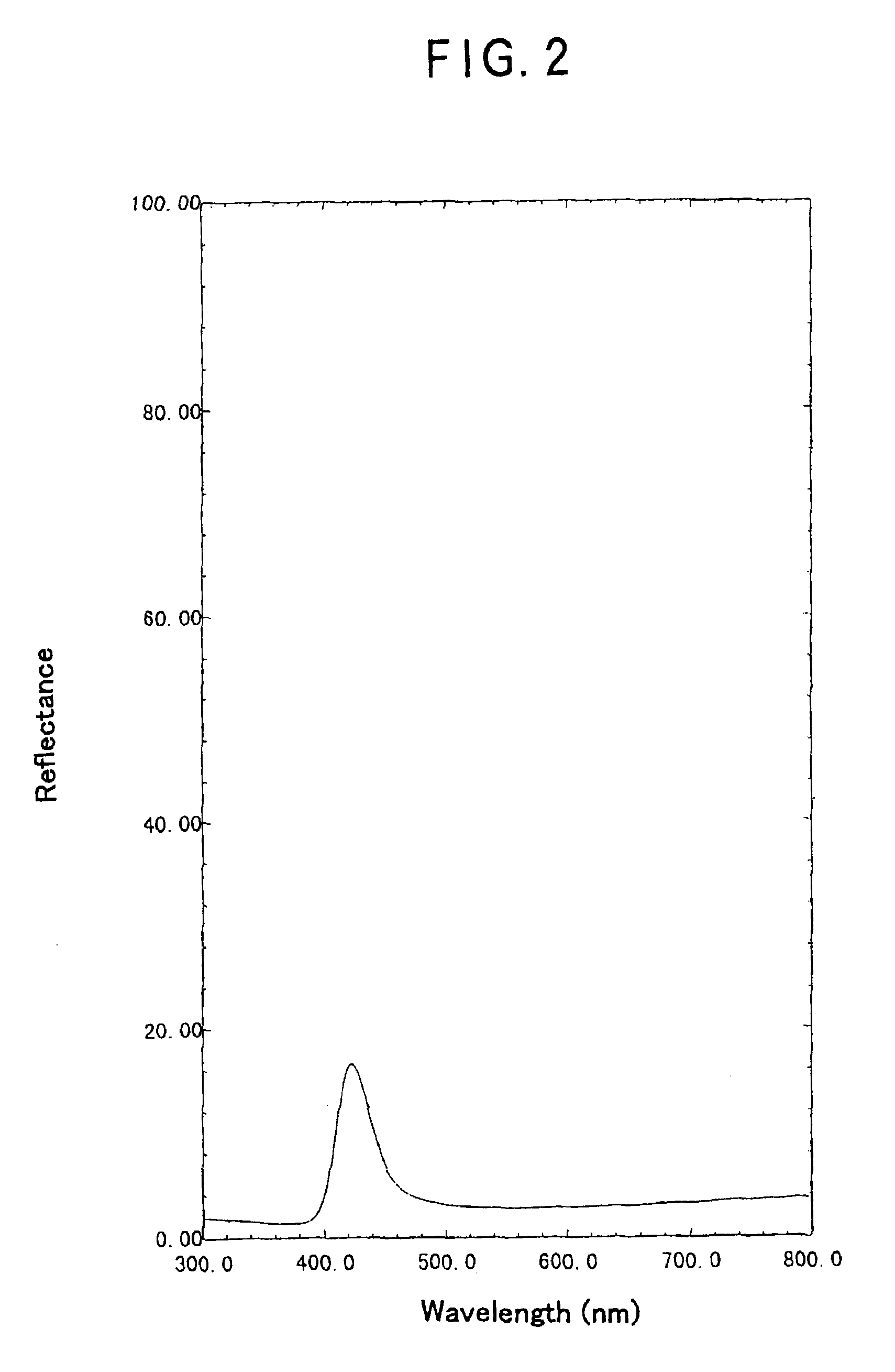
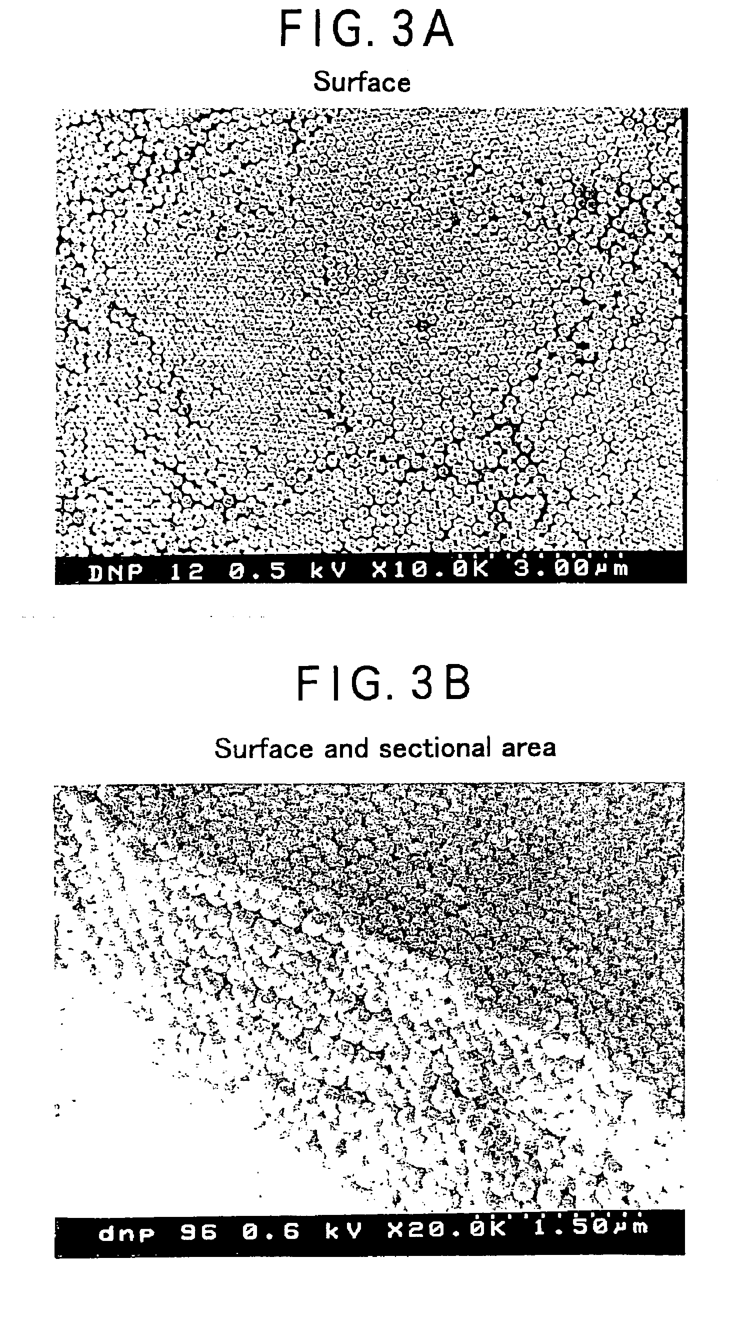
[0121]A polymer-particle composite obtained similarly to Example 1 was sintered at 750° C. for 3 hours to obtain a sintered silica particle. This sintered particle had the reflection spectrum (incidence: 50) shown in FIG. 2. A peak indicating that the silica particle was packed periodically (peak wavelength: 422.5 nm) also in the sintered composite was observed clearly. FIG. 3 shows a scanning electron microscopic photograph illustrating the surface and the sectional area of the sintered particle. It reveals that the particle was packed periodically on the surface and the sectional area.

example 3

[0122]A polymer-particle composite obtained similarly to Example 1 was sandwiched, as still being soaked with water without drying, between two glass substrates, the circumference of which was sealed to obtain a sealed material (artificial opal) which reflected a visible light like a naturally-occurring opal. This phenomenon indicated that a colloidal crystal was formed in this polymer-particle composite. FIGS. 4, 5 and 6 show the reflection spectra (FIG. 4: incidence: 5°, peak wavelength:540.5 nm, FIG. 5: incidence: 45°, peak wavelength:473.0 nm) and the transmission spectrum (FIG. 6: incidence: 0°, peak wavelength:538.0 nm) of this sealed material. Each figure revealed that the silica particle was packed periodically.


PUM

PropertyMeasurementUnit
Percent by massaaaaaaaaaa
Lengthaaaaaaaaaa
Lengthaaaaaaaaaa

Abstract

An objective of the invention is to provide a method for producing a polymer-particle composite by which a polymer-particle composite having a desired particle density and a desired film thickness can be produced conveniently without allowing the particle to be aggregated in the polymeric matrix. To accomplish the objective described above, the present invention provides a method for producing a polymer-particle composite comprising a step of forming a polymer-containing layer mainly consisting of a polymeric material and a step of bringing a particle suspension containing the particle suspended in a solvent capable of swelling the polymeric material into contact with the polymer-containing layer.

Description

CROSS REFERENCE TO RELATED APPLICATION[0001]This application claims the priority of Japanese patent application Serial No. P11-313522 filed on Nov. 4, 1999 and Japanese patent application Serial No. 2000-181594 filed on Jun. 16, 2000.BACKGROUND OF THE INVENTION[0002]The present invention relates to a method for producing a polymer-particle composite capable of forming a display material such as a light diffusion plate, an optical material such as a colloidal crystal, a building material such as a wallpaper, a noncombustible material, a catalyst material, a separation membrane, an electrode material, a decorative paper, a film, an accessory and a toy.[0003]Recently, there is an increasing interest on a nm- or μm-sized particle because of an industrial utility which varies depending on the particle size. For example, a dendrimer having a particle size of several nanometers to several ten nanometers has a specific property such as antenna effect, while a metal particle or a semiconduct...

Claims


Application Information

Patent Timeline
IPC IPC(8): B05D3/10B05D5/02G02B5/02B05D7/24C08J7/02C08K7/16C08L101/12G02B1/04
CPCB05D5/02B05D3/107
Inventor HATTORI, HIDESHI
Owner 3M INNOVATIVE PROPERTIES CO
Why Eureka
Try Eureka