Generation of viable cell active biomaterial patterns by laser transfer

a technology of laser transfer and active biomaterials, applied in the direction of vacuum evaporation coating, sputtering coating, railway signalling, etc., can solve the problems of inability to adapt to large-scale rapid prototyping, limit the flexibility and capability of these approaches, and wet techniques are inherently limited by viscoelastic properties, so as to improve existing tissue.

Inactive Publication Date: 2005-06-14
THE UNITED STATES OF AMERICA AS REPRESENTED BY THE SECRETARY OF THE NAVY
View PDF30 Cites 38 Cited by
  • Summary
  • Abstract
  • Description
  • Claims
  • Application Information

AI Technical Summary

Benefits of technology

[0067]The embodiments described above can be combined in many ways, allowing for the deposition of complex multi-layer, multi-component structures with a wide range of uses and applications. The examples demonstrate the capability of placing biomaterials (proteins, a cell, or group of cells) onto various surfaces in a computer-controlled fashion and on a 10's of micron scale. This ability allows the making of many structures and devices that require cells or other biomaterials to be placed in patterns or 3D shapes where there is microscopic structure. The following describes devices and their uses that could be made using the method of the invention. These descriptions of devices are not intended to limit the scope of the invention.
[0068]1) Engineered cellular or composite structures for growth, repair, replacement, or improvement of tissue: Tissue is comprised of precisely organized cells and biomolecules. Live tissue can be built from these components (using cells as bricks and biomolecules as mortar) by building complex cell structures in a computer-controlled manner. A specific goal would be to use this tissue to implant it in the body to heal or improve existing tissue.
[0069]2) Living organs: Organs are even more complicated tissue structures that perform specific life-sustaining functions in the body. They contain s...

Problems solved by technology

(Direct writing may also be accomplished in the sub-micron range using electron beams or focused ion beams, but these techniques, because of their small scale, are not appropriate for large-scale rapid prototyping.)
The solvent or binder must later be removed by a drying or curing process, which limits the flexibility and capability of these approaches.
In addition, wet techniques are inherently limited by viscoelastic properties of the fluid in which the particles are suspended or dissolved.
Because the film material is vaporized by the action of the laser, laser induced forward transfer is inherently a homogeneous, pyrrolytic technique and typically cannot be used to deposit complex crystalline, multi-component materials or materials that have a crystallization temperature well above room temperature because the resulting deposited material will be a weakly adherent amorphous coating.
Moreover, because the material to be transferred is vaporized, it becomes more reactive and can more easily become degraded, oxidized, or contaminated.
The method is not well suited for the transfer of organic materials, since many organic materials are fragile, thermally labile, and can be irreversibly damaged during de...

Method used


Image

  • Generation of viable cell active biomaterial patterns by laser transfer
  • Generation of viable cell active biomaterial patterns by laser transfer
  • Generation of viable cell active biomaterial patterns by laser transfer

Examples


example 1

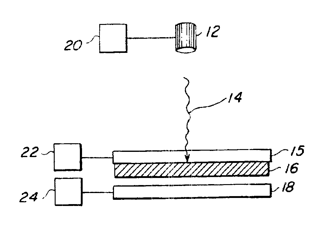
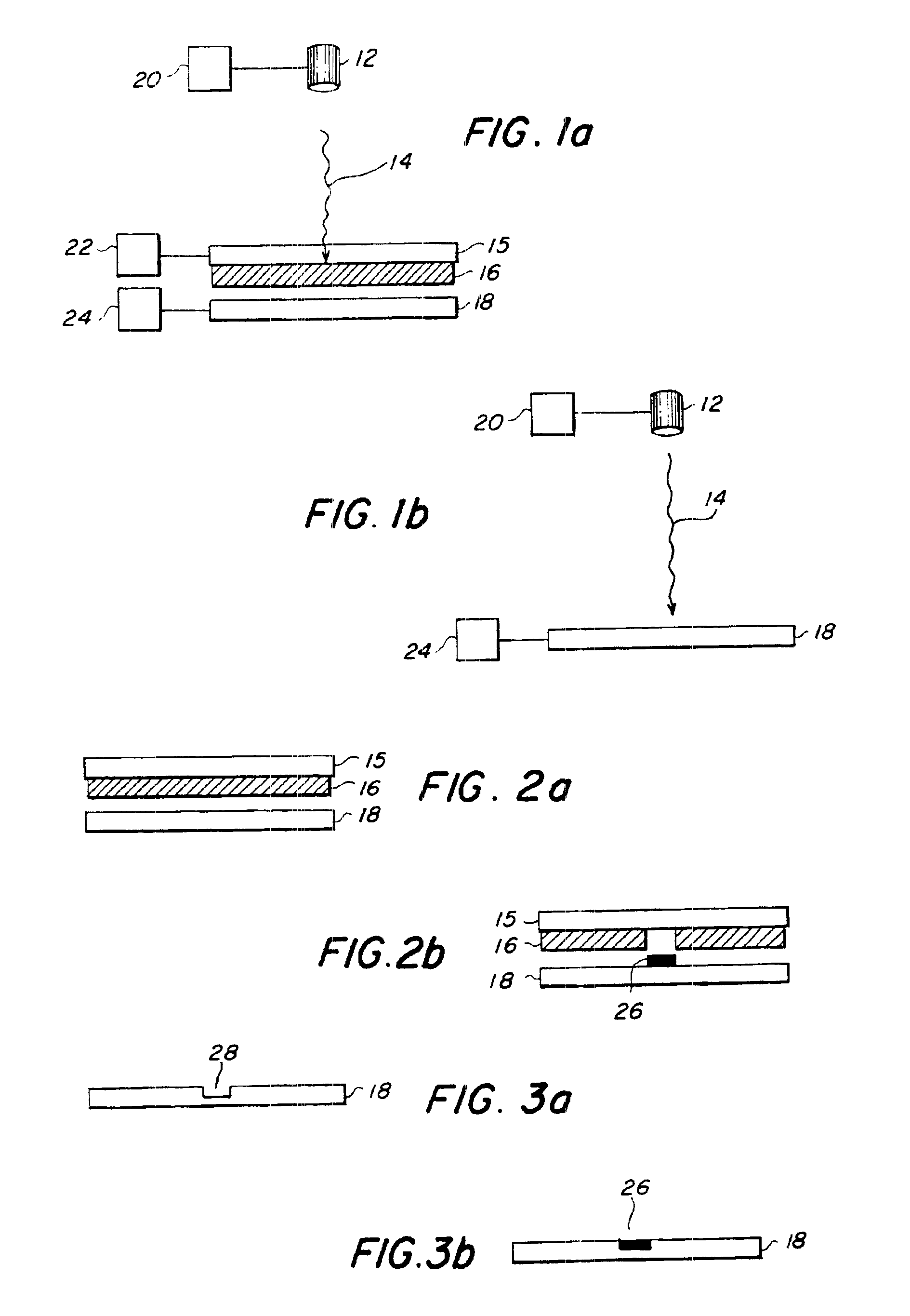
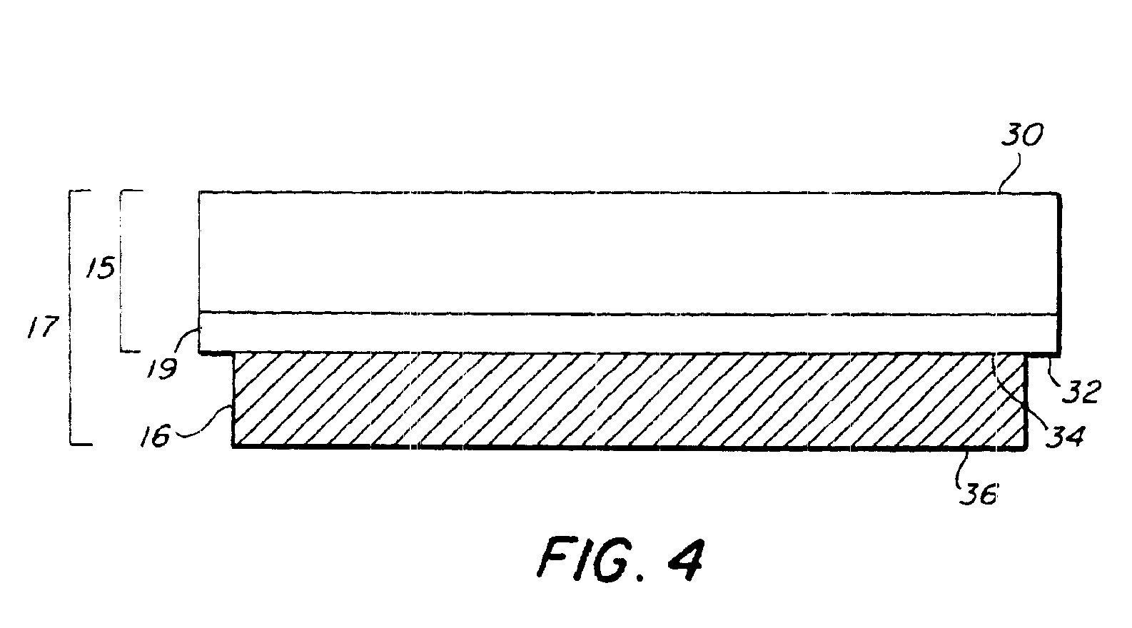
[0082]Transfer of living E. coli bacteria from a frozen support—The transfer material was living E. coli cells. The matrix material was Luria-Bertani (LB) broth and kanamycin (50 μg / ml). The spot size was 0.09 cm2 and the 193 nm energy density was 0.2 J / cm2. The composite material 16 was frozen to the laser-transparent support 15. SEM micrographs showed that there was no damage to the transferred cells.

example 2

[0083]Transfer of living E. coli bacteria from a room temperature support—The transfer material was living E. coli cells. The matrix material was LB broth, agar, and kanamycin. The composite material 16 was coated on the laser-transparent support 15 and kept at room temperature. The same laser parameters as above resulted in successful transfer.

example 3

[0084]Transfer of living E. coli bacteria from a room temperature support—The transfer material was living GFP marked E. coli cells. The matrix material was LB broth, kanamycin, glycerin, and barium titanate nanoparticles. This transfer was performed with a different pulsed UV laser at 355 nm, a spot size of 65 microns, and an energy density of 1 J / cm2. A SEM micrograph taken under UV light showed fluorescent activity in the transferred cells, proving that the cells were still living.


PUM

PropertyMeasurementUnit
Temperatureaaaaaaaaaa

Abstract

A method for depositing a transfer material onto a receiving substrate uses a source of laser energy, a receiving substrate, and a target substrate. The target substrate comprises a laser-transparent support having a laser-facing surface and a support surface. The target substrate also comprises a composite material having a back surface in contact with the support surface and a front surface. The composite material comprises a mixture of the transfer material to be deposited and a matrix material. The matrix material is a material that has the property that, when it is exposed to laser energy, it desorbs from the laser-transparent support. The source of laser energy is positioned in relation to the target substrate so that laser energy is directed through the laser-facing surface of the target substrate and through the laser-transparent support to strike the composite material at a defined target location. The receiving substrate is positioned in a spaced relation to the target substrate. The source of laser energy has sufficient energy to desorb the composite material at the defined target location, causing the composite material to desorb from the defined target location and be lifted from the support surface of the laser-transparent support. The composite material is deposited at a defined receiving location on the receiving substrate. The method is useful for creating a pattern of biomaterial on the receiving substrate.

Description

[0001]This nonprovisional application is a continuation-in-part application of U.S. patent application Ser. No. 09 / 671,166 filed on Sep. 28, 2000, now U.S. Pat. No. 6,766,764 which is a divisional application of Ser. No. 09 / 318,134, now U.S. Pat. No. 6,177,151 filed on May 25, 1999, which claims benefit of U.S. provisional patent application 60 / 117,468 filed on Jan. 27, 1999. This application also claims benefit of U.S. provisional patent application 60 / 269,384 filed on Feb. 20, 2001 as to certain matter. All applications and patents named above are incorporated herein by reference.BACKGROUND OF THE INVENTION[0002]1. Field of the Invention[0003]The invention relates generally to a method for the deposition of materials and more specifically to a method for direct writing of a wide range of different biomaterials onto a substrate.[0004]2. Description of the Prior Art[0005]The term “direct write” refers generally to any technique for creating a pattern directly on a substrate, either ...

Claims


Application Information

Patent Timeline
IPC IPC(8): B01J19/00C23C14/04C23C14/28H05K3/02H05K3/04C07B61/00C40B40/18C40B60/14
CPCB01J19/0046H05K3/046B82Y30/00C23C14/048C23C14/28B01J2219/00441B01J2219/00527B01J2219/00585B01J2219/0059B01J2219/00596B01J2219/00605B01J2219/00612B01J2219/00626B01J2219/00659B01J2219/00677B01J2219/00689B01J2219/0072B01J2219/0074B01J2219/00745B01J2219/0075C40B40/18C40B60/14G01N2001/2886B01J2219/00317H05K3/1275H05K2203/107H05K3/4664H05K3/467
Inventor RINGEISEN, BRADLEY R.CHRISEY, DOUGLAS B.PIQUE, ALBERTOMCGILL, R. ANDREW
Owner THE UNITED STATES OF AMERICA AS REPRESENTED BY THE SECRETARY OF THE NAVY
Why Eureka
Try Eureka