Short contact time catalytic partial oxidation process for recovering sulfur from an H2S containing gas stream

a technology of catalytic partial oxidation and h2s, which is applied in the direction of sulfur preparation/purification, separation processes, physical/chemical process catalysts, etc., can solve the problems of hydrogen sulfide content, h/sub>2/sub> h2s, in concentrated form, etc., to achieve the effect of reducing the toxicity of hydrogen sulfide-containing gases and liquids, reducing the toxicity of reducing

Inactive Publication Date: 2005-09-20
PHILLIPS 66 CO
View PDF56 Cites 60 Cited by
  • Summary
  • Abstract
  • Description
  • Claims
  • Application Information

AI Technical Summary

Benefits of technology

[0032]In some embodiments, the process of removing sulfur from an H2S containing hydrocarbon stream employs a sulfur resistant catalyst device that made by a method that includes avoiding exposure of said catalytic material to a sulfur-containing compound at a temperature at which sulfur can chemically react with or physically deposit on said catalytic material. According to preferred embodiments, the process also includes heating the catalytic material, in the presence of a light hydrocarbon, to a temperature sufficient to cause at least a portion of the catalytic material to associate with carbon in the same chemical phase.
[0033]An advantage provided by certain embodiments of the present invention is that existing proce...

Problems solved by technology

The hydrogen sulfide content is problematic.
Not only does it have an intensely unpleasant odor, it is also toxic and constitutes an unwanted component in the end products produced from the natural gas.
A drawback of working with the H2S-containing LPG is that the H2S, in concentrated form, is extremely corrosive to the steel pipes and containers used to transport the hydrogen sulfide-containing gases and liquids.
As a result of all of the above-described problems, H2S-containing natural gas formations have tended to be underutilized in the petroleum industry.
While various methods exist for removing hydrogen sulfide from gases and liquids during petroleum processing, most of those processes require large, expensive Claus plants, or modified Claus plants, for extracting and processing the sulfur.
Conventional desulfurization operations are not practical for use at small operations such as remote well sites or on natural gas producing off shore oil platforms.
The Claus process is not suitable for use in cleaning up hydrogen or light hydrocarbon gases (such as natural gas) that contain H2S, however.
Not only is the hydrocarbon content lost in the initial thermal combustion step of the Claus process, but carbon, carbonyl sulfide and carbon disulfide which are produced cause catalyst fouling and dark sulfur.
Moreover, carbonyl sulfide is difficult to convert to elemental sulfur.
Most direct oxidation methods are applicable to sour gas streams containing relatively small amounts of H2S and large amounts of h...

Method used


Image

  • Short contact time catalytic partial oxidation process for recovering sulfur from an H2S containing gas stream
  • Short contact time catalytic partial oxidation process for recovering sulfur from an H2S containing gas stream
  • Short contact time catalytic partial oxidation process for recovering sulfur from an H2S containing gas stream

Examples


example 1

Petroleum Hydrotreater

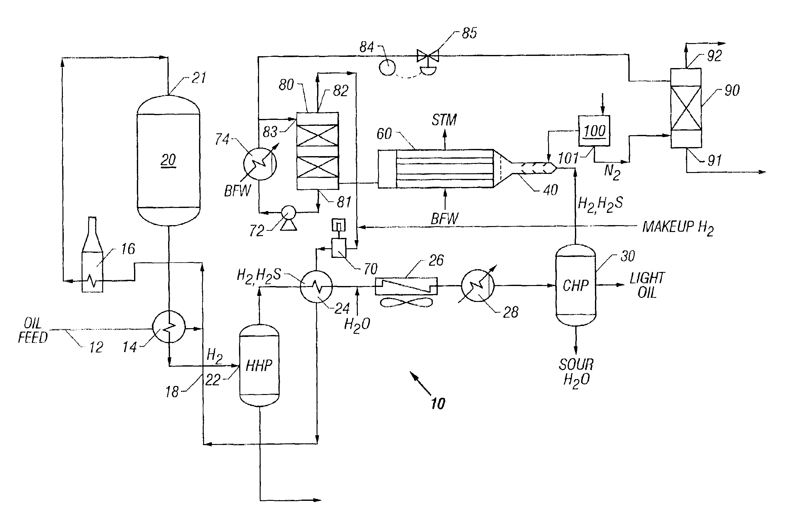
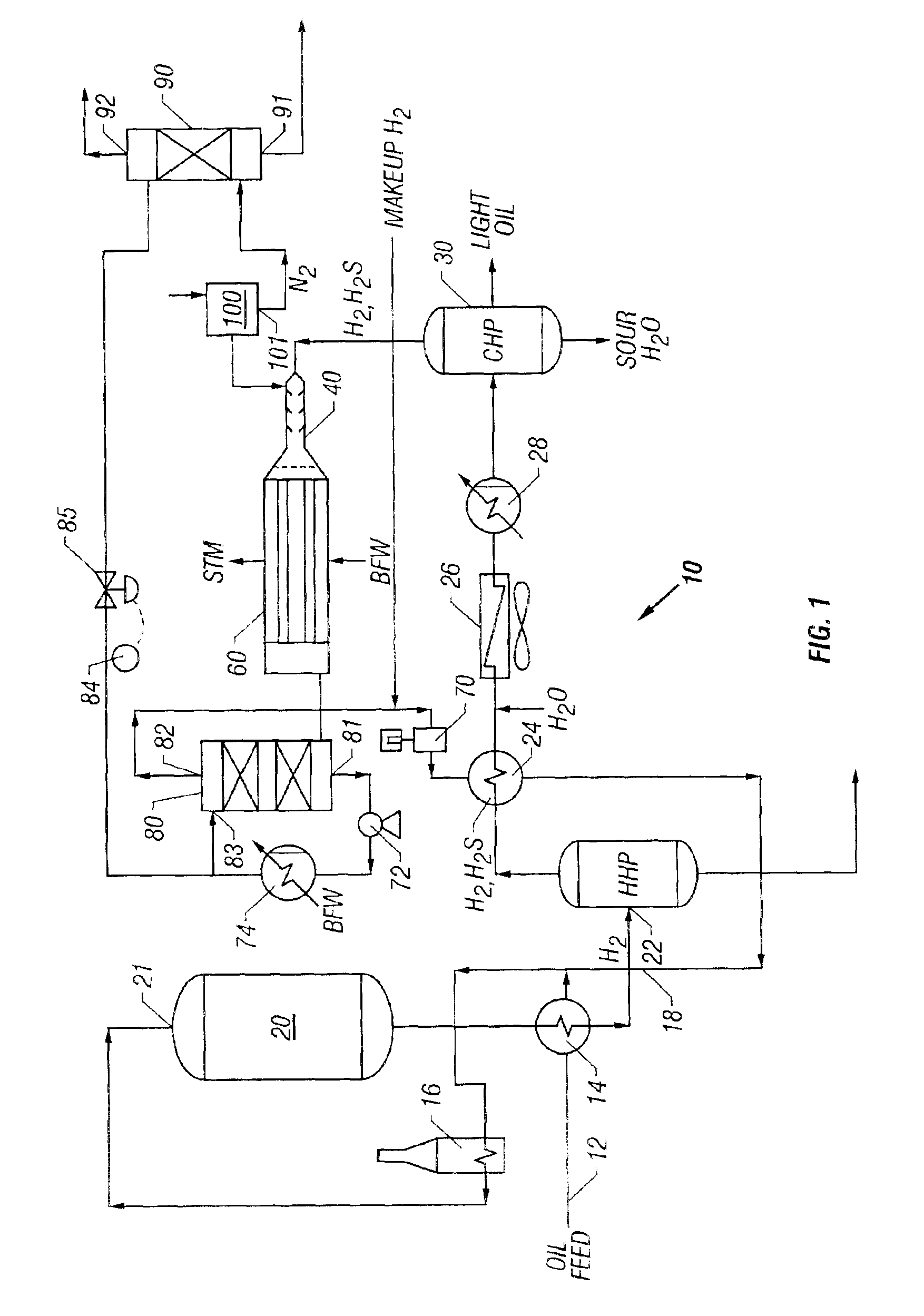
[0056]A refinery hydrodesulfurization (HDS) plant is used to illustrate one embodiment of an improved sulfur removal system and process. The new process for H2S conversion can also be used with a feedstock consisting of practically any gas containing H2S, and the new sulfur removal unit may be placed in-line with many other compatible systems which require a H2S removal step. Referring to FIG. 1, a flow diagram of a preferred embodiment of a refinery hydrodesulfurizer (HDS) or hydrotreater system is shown. HDS system 10 generally includes oil feed inlet 12, feed / effluent heat exchanger 14, charge heater 16, hydrodesulfurization reactor 20, hot high pressure (HHP) separator 22, hydrogen heat recovery unit 24, air cooler 26, water cooler 28, cold high pressure (CHP) separator 30, short contact time reactor 40, waste heat boiler 60, recycle H2 compressor 70, sulfur condenser 80, sulfur degassing drum 90 and air separator 100. A basic HDS plant configuration, such ...

example 2

Purification of a Natural Gas Stream Containing H2S

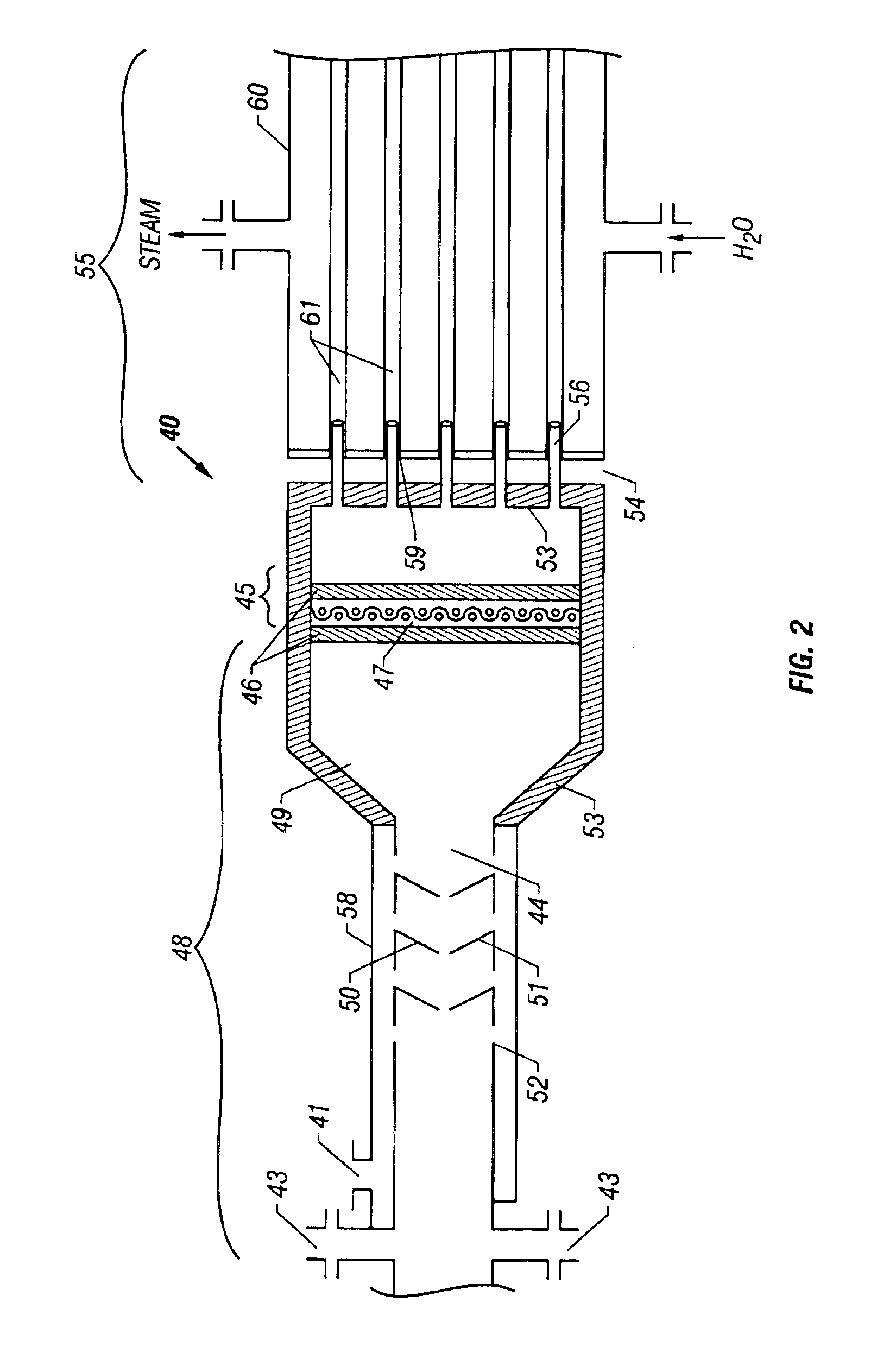
[0071]Referring to FIG. 3, a diagram of a preferred embodiment of a natural gas desulfurizing system 100 is shown. System 100 generally includes a short contact time reactor 140 with a natural gas stream inlet 143, an O2 inlet 141, a heat exchanger such as waste heat boiler 160, and sulfur condenser 180. Reactor 140 is like reactor 40 described in Example 1 and shown in FIG. 2. Following waste heat boiler 160 is sulfur condenser 180, which has a liquid sulfur outlet 181 and a desulfurized gas outlet 182.

[0072]In operation, a natural gas stream that contains a quantity of H2S and an O2-containing stream are injected into inlets 143, 141, respectively. Apparatus that is well known in the art for injecting gas into short contact time reactors at high flow rates is employed to feed the reactant gases at atmospheric or superatmospheric pressure. Oxygen entering reactor 140 via inlet 141 is mixed with the H2S / natural gas stream in mixing ...


PUM

PropertyMeasurementUnit
Temperatureaaaaaaaaaa

Abstract

A process for removing sulfur from a H2S-containing gas stream is disclosed. A preferred embodiment of the process comprises incorporating a short contact time catalytic partial oxidation reactor, a cooling zone, and a condenser into a conventional refinery or gas plant process, such as a natural gas desulfurizer, a hydrotreater, coker or fluid catalytic cracker, in which sulfur removal is needed in order to produce a more desirable product. An H2S-containing gas stream is fed into a short contact time reactor where the H2S is partially oxidized over a suitable catalyst in the presence of O2 to elemental sulfur and water.

Description

CROSS REFERENCE TO RELATED APPLICATIONS[0001]This application claims the benefit under 35 U.S.C. §119(e) of U.S. Provisional Patent Application No. 60 / 256,440 filed Dec. 18, 2000. This application is also a continuation-in-part of U.S. patent application Ser. No. 09 / 742,999 filed Dec. 20, 2000 (U.S. Pat No. 6,579,510), which is a continuation-in-part of U.S. patent application Ser. No. 09 / 625,710 filed Jul. 25, 2000, abandoned, that claims the benefit under U.S.C. §119(e) of U.S. Provisional Patent Application No. 60 / 146,635 filed Jul. 30, 1999.BACKGROUND OF THE INVENTION[0002]1. Technical Field of the Invention[0003]The present invention generally relates to methods of desulfurizing H2S-containing gas streams. More particularly, the present invention relates to sulfur recovery processes employing the catalyzed direct partial oxidation of H2S to elemental sulfur and water and to catalyst compositions that are active for catalyzing that process.[0004]2. Description of the Related Art...

Claims


Application Information

Patent Timeline
IPC IPC(8): B01D53/86B01J8/02B01J23/40B01J35/00B01J35/04C01B3/00C01B3/38C01B17/04C01B17/00
CPCB01D53/8612B01J8/0221B01J23/40B01J35/04C01B3/386C01B17/0413C01B17/046B01J2208/00256B01J2208/00274B01J2208/0053B01J2208/00849B01J2208/00884B01J2208/021B01J2219/00006C01B2203/0261C01B2203/0415C01B2203/045C01B2203/0485C01B2203/0495C01B2203/061C01B2203/062C01B2203/0805C01B2203/0811C01B2203/0877C01B2203/0883C01B2203/0894C01B2203/1005C01B2203/1023C01B2203/1041C01B2203/1052C01B2203/1064C01B2203/1082C01B2203/1241C01B2203/127C01B2203/1282C01B2203/146C01B2203/1604C01B2203/1695Y02P20/52
Inventor KELLER, ALFRED E.ALLISON, JOE D.RAMANI, SRIRAMPRUITT, TERRY D.
Owner PHILLIPS 66 CO
Why Eureka
Try Eureka