Laser element, method of producing the laser element, and a laser module employing the laser element

a laser element and laser module technology, applied in the direction of semiconductor laser arrangement, semiconductor laser structure details, semiconductor lasers, etc., can solve the problems of high significant decrease in coupling efficiency, and inability to fix the nitride-based semiconductor laser bar to the heat sink, so as to facilitate the design and alignment of optical systems and manufacture of laser modules , the effect of increasing the coupling efficiency to the optical fiber

Inactive Publication Date: 2006-10-10
ADTEC ENG +1
View PDF2 Cites 2 Cited by
  • Summary
  • Abstract
  • Description
  • Claims
  • Application Information

AI Technical Summary

Benefits of technology

[0025]When the laser element according to the first aspect of the present invention is used in a laser module in which laser beams are optically multiplexed in an optical fiber, it is sufficient to align the optical axes of lenses corresponding to the light-emission points along the surface shape of the heat sink, since the light-emission points are aligned along the surface shape of the heat sink. Thus, according to the fourth aspect of the present invention, designing and alignment of the optical system and manufacture of the laser module are facilitated.
[0026]In addition, since the laser module according to the third aspect of the present invention uses the laser element which exhibits high reliability over time as mentioned before, it is possible to increase the coupling efficiency to the optical fiber through the optical system.

Problems solved by technology

In the case of the typical optical fiber having a radius of 25 micrometers, the above displacement causes significant decrease in the coupling efficiency.
In addition, when indium is used as a soft brazing material, it is impossible to fix the nitride-based semiconductor laser bar to the heat sink so that the nitride-based semiconductor laser bar has a shape equivalent to the surface shape of a heat sink, because the hardness of the nitride-based semiconductor laser bar is high.
Further, in the case where nitride-based semiconductor laser bars are used in laser modules as mentioned before, the aforementioned curvature decreases the coupling efficiency to the optical fiber.

Method used


Image

  • Laser element, method of producing the laser element, and a laser module employing the laser element
  • Laser element, method of producing the laser element, and a laser module employing the laser element
  • Laser element, method of producing the laser element, and a laser module employing the laser element

Examples


first embodiment

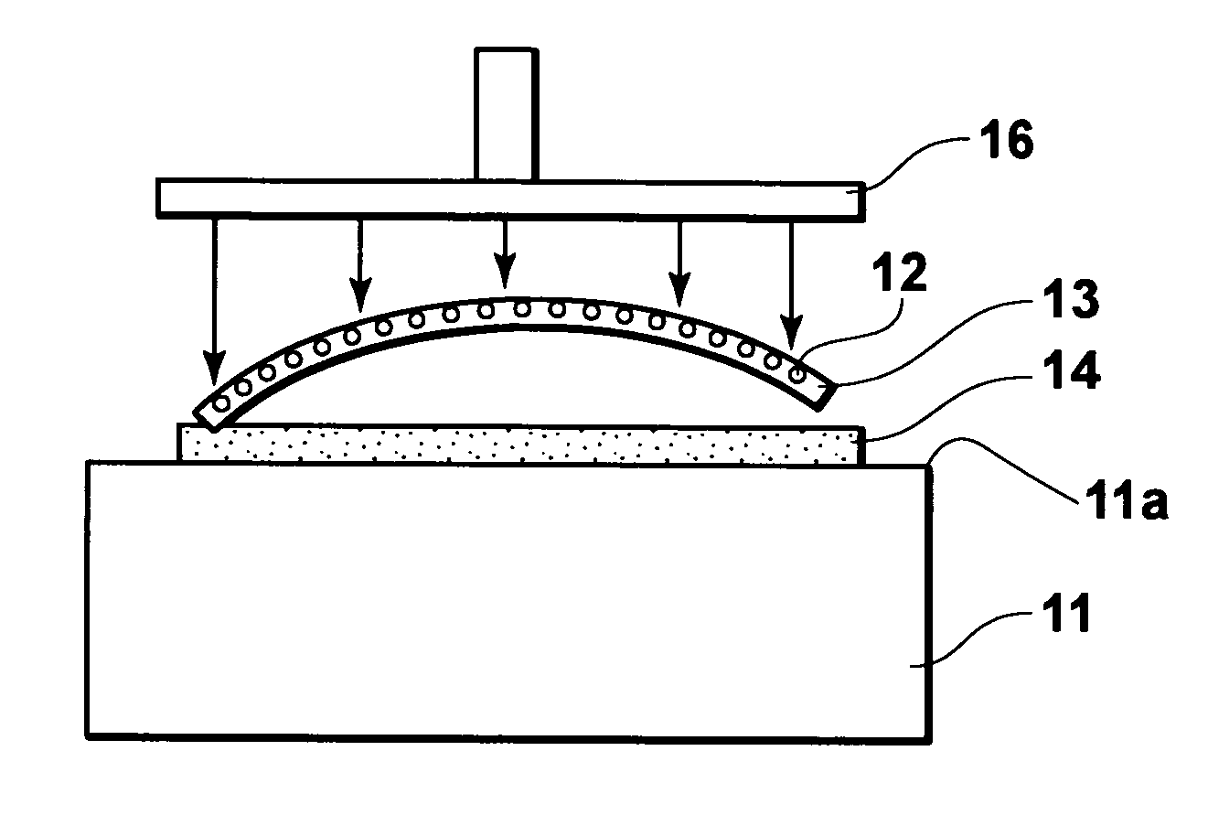
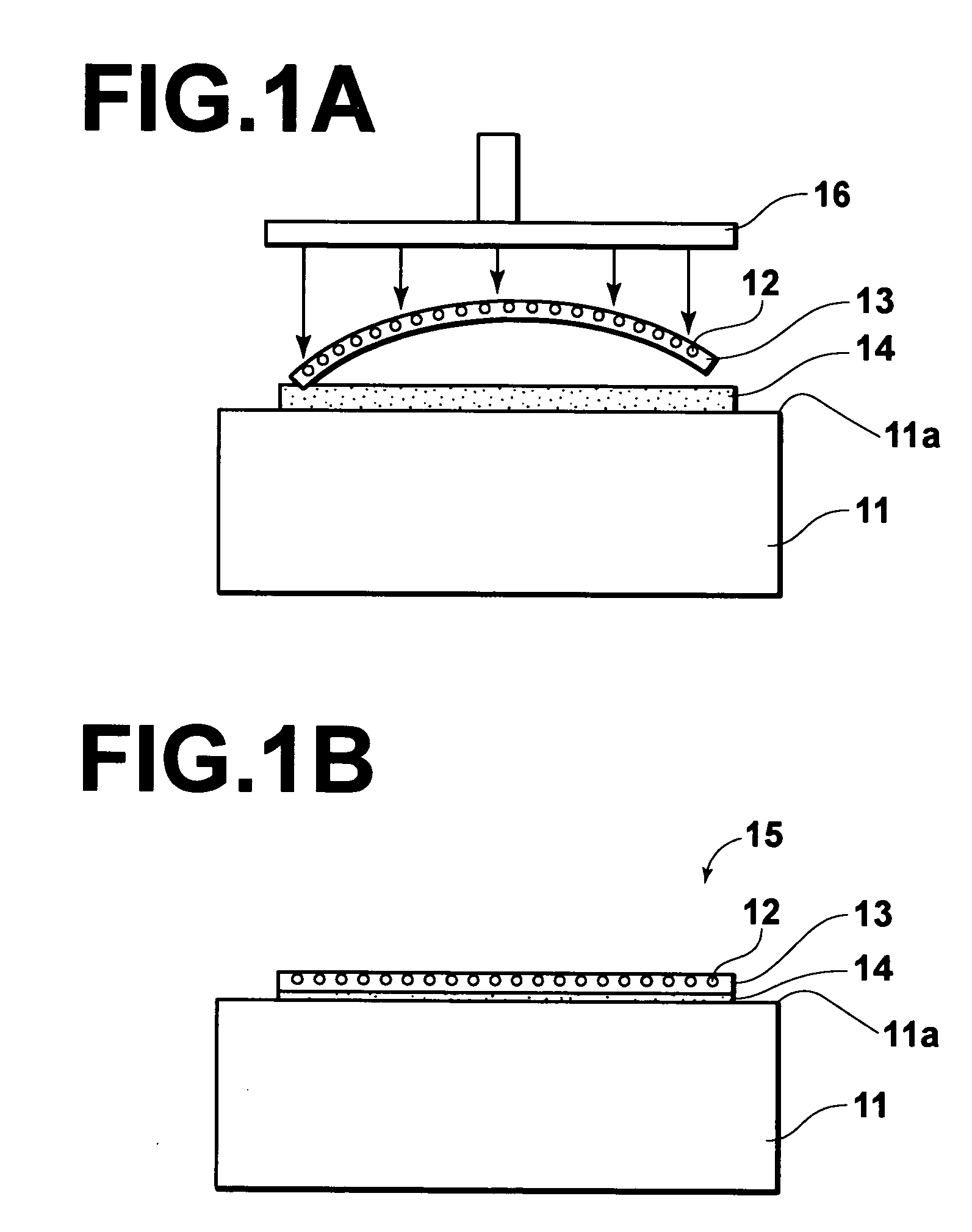
[0039]A process for producing a laser element according to the first embodiment of the present invention is explained below. FIGS. 1A and 1B are cross-sectional views of initial and final stages of the process for producing the laser element according to the first embodiment.

[0040]As illustrated in FIG. 1A, an AuSn brazing material 14 in pellet form having a thickness of about 3 to 50 micrometers is placed on a flat surface 11a of a heat sink 11, which is made of copper and plated in such a manner that the outermost layer of the plating is gold and has a thickness of about 1 micrometer. Then, a nitride-based semiconductor laser bar 13 is fixed to the heat sink 11 by placing the nitride-based semiconductor laser bar 13 on the brazing material 14, and heating, melting, and then solidifying the brazing material 14 while pressing the nitride-based semiconductor laser bar 13 toward the heat sink 11 with a bonding collet 16, which is constituted by a flat plate corresponding to the shape ...

second embodiment

[0066]A laser module according to the second embodiment of the present invention, which uses the laser element according to the first embodiment of the present invention is explained below. FIG. 6 is a plan view illustrating an outline of the construction of the laser module according to the second embodiment of the present invention.

[0067]As illustrated in FIG. 6, the laser module according to the second embodiment comprises a laser element 15, an optical system, and a single multimode optical fiber 63. In the laser element 15, a nitride-based semiconductor laser bar 13 having twenty light-emission points and a length of 1 cm is fixed to a heat sink 11 made of copper with an AuSn brazing material, where the light-emission-point displacement is 0.2 micrometers. The optical system is constituted by a collimator-lens array 61 and a condensing lens 62.

[0068]Although the nitride-based semiconductor laser bar 13 emits twenty laser beams B1 through B20, in order to simplify the illustrati...

third embodiment

[0081]A process for producing a laser element according to the third embodiment of the present invention is explained below. FIGS. 8A and 8B are cross-sectional views of initial and final stages of the process for producing the laser element according to the third embodiment. In FIGS. 8A and 8B, elements which are equivalent to corresponding elements in FIGS. 1A and 1B bear the same references as the corresponding elements in FIGS. 1A and 1B.

[0082]As illustrated in FIG. 8A, an AuSn brazing material 14 having a thickness of about 3 to 50 micrometers is deposited by evaporation on a cylindrical surface 73a of a heat sink 73, which is made of copper and coated by evaporation with nickel, platinum, and gold films respectively having thicknesses of 0.1, 0.2, and 1 μm. Then, the nitride-based semiconductor laser bar 13 is fixed to the heat sink 73 by placing the nitride-based semiconductor laser bar 13 on the brazing material 14, and heating, melting, and then solidifying the brazing mate...


PUM

PropertyMeasurementUnit
radiusaaaaaaaaaa
thicknessaaaaaaaaaa
thicknessaaaaaaaaaa

Abstract

In a method for producing a laser element, a brazing material is placed between a nitride-based semiconductor laser bar and a fixation surface of a heat sink, where the brazing material contains gold and one of tin and silicon as main components, the nitride-based semiconductor laser bar has at least three light-emission points formed on a substrate, the heat sink is made of copper or copper alloy, and the fixation surface has a predetermined shape. Then, the nitride-based semiconductor laser bar is fixed to the fixation surface of the heat sink by melting and solidifying the brazing material while pressing the nitride-based semiconductor laser bar toward the heat sink with a tool having a shape corresponding to the predetermined shape of the fixation surface.

Description

BACKGROUND OF THE INVENTION[0001]1. Field of the Invention[0002]The present invention relates to a laser element in which a laser bar being made of nitride-based semiconductor materials and containing a plurality of light-emission points formed on a single substrate is fixed to a heat sink. The present invention also relates to a process for producing the above laser element. The present invention further relates to a laser module containing the above laser element.[0003]2. Description of the Related Art[0004]The following documents (1) and (2) disclose information related to the present invention.[0005](1) U.S. patent Laid-Open No. 20020090172[0006](2) Roland Dichel (ed.), “High-Power Diode Lasers: Fundamentals, Technology, Applications, With Contributions by Numerous Experts,” Springer-Verlag, 2000[0007]In order to increase laser output power, laser modules which comprise at least one laser-light source for emitting a plurality of laser beams, an optical fiber, and an optical syst...

Claims


Application Information

Patent Timeline
Patent Type & Authority Patents(United States)
IPC IPC(8): H01S3/04G02B6/42H01L21/52H01S5/00H01S5/02H01S5/022H01S5/024H01S5/32H01S5/323H01S5/343H01S5/40
CPCH01S5/02272H01S5/02469H01S5/4031H01S5/0014H01S2304/12H01S5/0213H01S5/02252H01S5/02284H01S5/3202H01S5/3216H01S5/32341H01S5/4012H01S2301/173H01S2304/04H01S5/005H01S5/02326H01S5/0237H01S5/02251H01S5/02365H01S5/4025
Inventor YAMANAKA, FUSAOKURAMACHI, TERUHIKO
Owner ADTEC ENG
Why Eureka
Try Eureka