Method of constructing a unitary amorphous metal component for an electric machine

Active Publication Date: 2006-12-05
METGLAS INC
View PDF51 Cites 32 Cited by
  • Summary
  • Abstract
  • Description
  • Claims
  • Application Information

AI Technical Summary

Benefits of technology

[0024]The advantages afforded by the present invention include simplified manufacturing, reduced manufacturing time, decreased stresses (e.g., magnetostrictive) encountered during construction of bulk amorphous metal components, and optimized performance of the finished amorphous metal magnetic component. Especially beneficial is the elimination of process steps previously required to form and stack a large number of individually punched laminations. Conventional punching dies are expensive to construct and have limited usable life when stamping amorphous metal. Moreover, the present process is more flexible in accommodating design changes without the detriment of having to amortize die fabrication costs over a large production run. Motors having large diameters can be made readily with efficient utilization of magnetic material that does not result in excessive production of unusable scrap. These benefits are difficult or impossi

Problems solved by technology

Such magnetization is needed to drive the motor; but causes unavoidable losses due to magnetic hysteresis.
These losses contribute to an overall reduction in motor efficiency.
Axial flux designs are much less commonly used, in part because of the lack of suitable means for constructing components having the requisite electromagnetic properties and adequate mechanical integrity.
Although amorphous metals offer superior magnetic performance, including reduced hysteresis losses, when compared to non-oriented electrical steels, they have widely been regarded as not suitable for use in electric motors due to certain physical properties and the resulting impediments to conventional fabrication.
Consequently, conventional cutting and stamping processes cause fabrication tools and dies to wear more rapidly.
The resulting increase in the tooling and manufacturing costs makes fabricating amorphous metal components such as rotors and stators using conventional techniques commercially impractical.
The thinness of amorphous metals also translates into an increase in the number of laminations required for a component of a given stack height, further increasing its total manufacturing cost.
However, amorphous metal is a very hard material, making it very difficult to cut or form easily.
Once annealed to achieve peak magnetic properties, it becomes very brittle, making it difficult and expensive to use conventional approaches to construct amorphous metal magnetic components.
The brittleness of amorphous metal also causes concern for the durability of a motor or generator that utilizes amorphous metal magnetic components.
These magnetic forces are capable of placing considerable stresses on the stator material, and may damage an amorphous metal magnetic stator.
Another problem with amorphous metal magnetic components is that the magnetic permeability of amorphous metal material is reduced w

Method used


Image

  • Method of constructing a unitary amorphous metal component for an electric machine
  • Method of constructing a unitary amorphous metal component for an electric machine
  • Method of constructing a unitary amorphous metal component for an electric machine

Examples


example 1

Preparation And Electro-Magnetic Testing of a Unitary Amorphous Metal Motor Stator

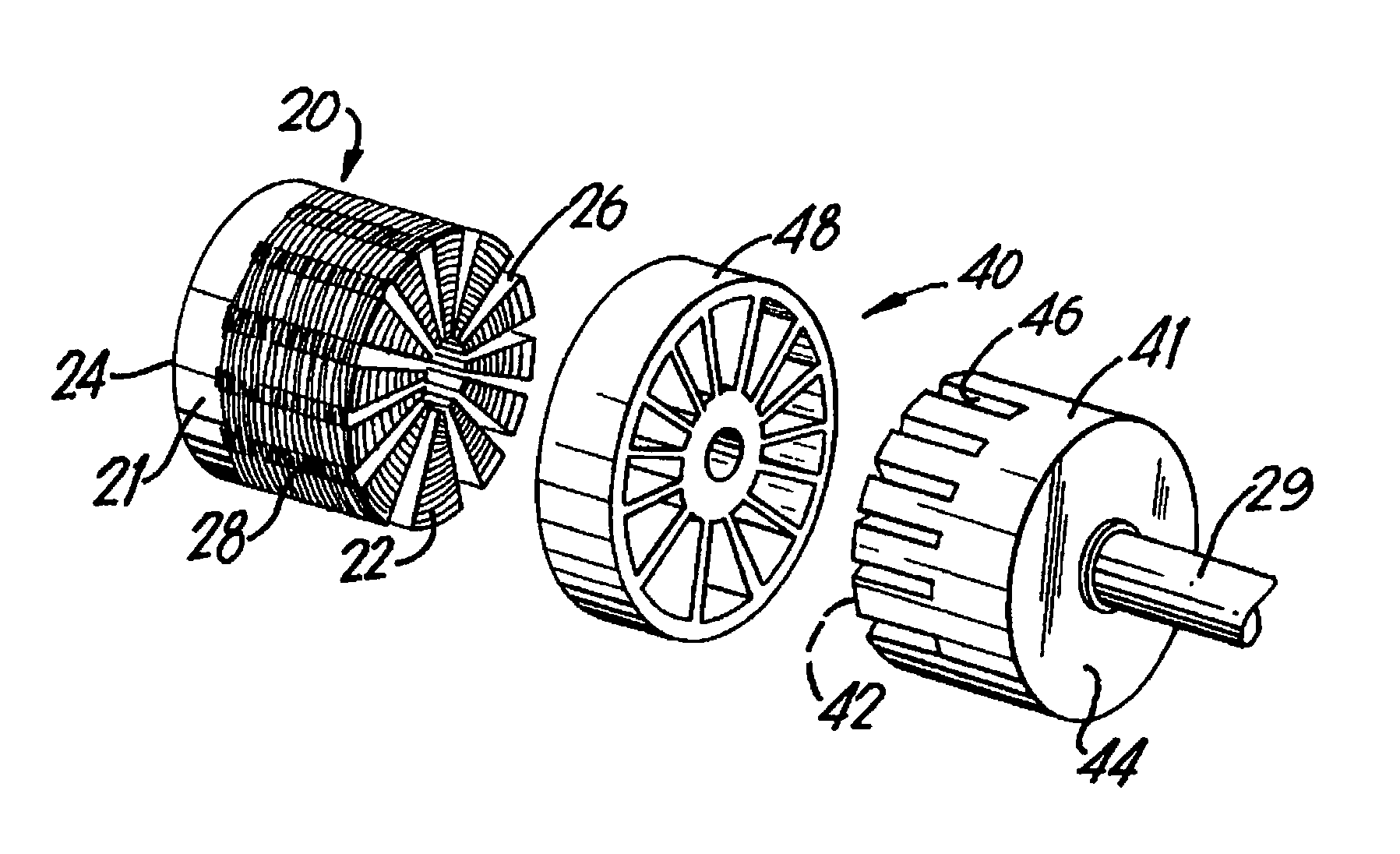
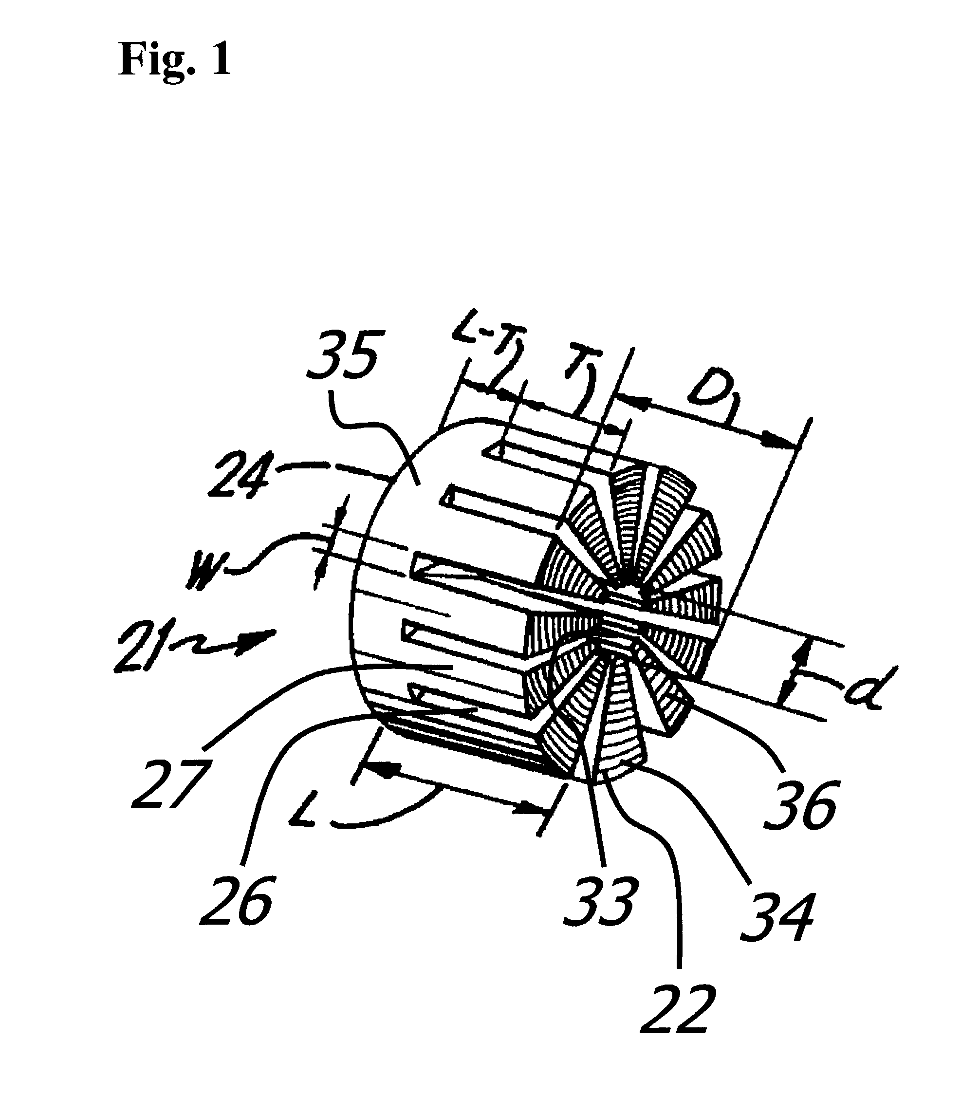
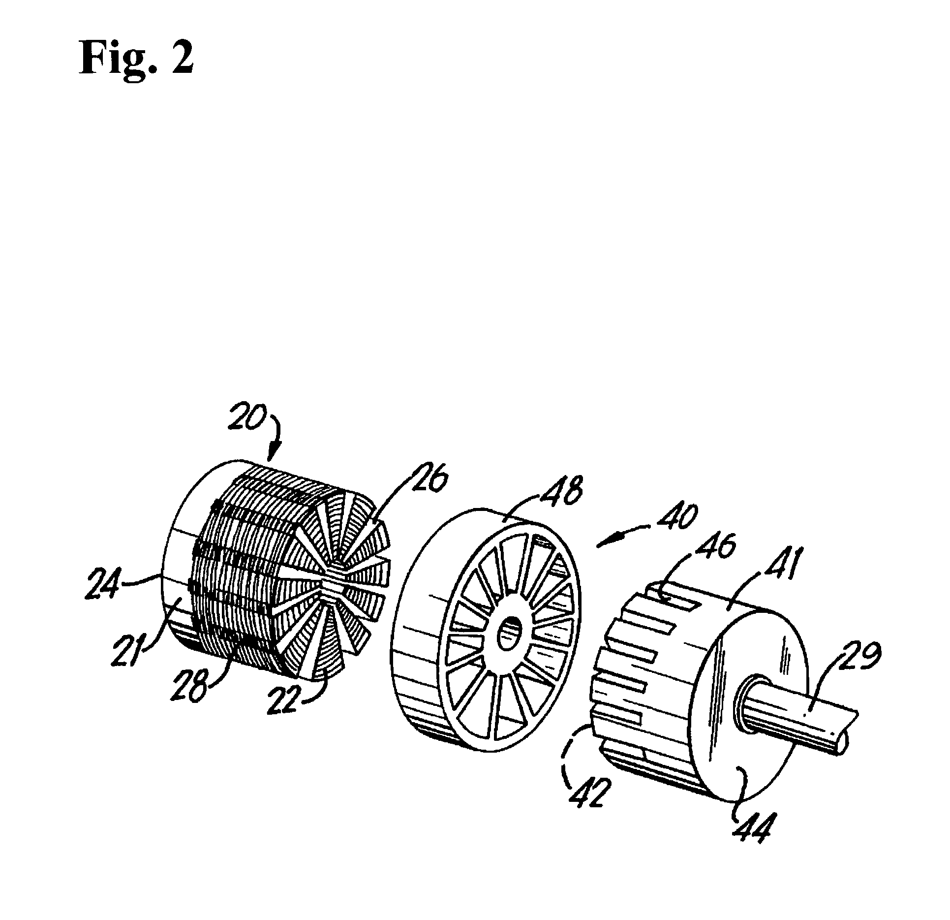
[0067]Fe80B11Si9 ferromagnetic amorphous metal ribbon, approximately 26.7 mm wide and 0.022 mm thick, is spirally wound to form two substantially identical right circular cylinder assemblies, each having about 3300 layers, an outside diameter of 422 mm, and an inside diameter of 272 mm, as illustrated in FIG. 1. The cylindrical assemblies are annealed in a nitrogen atmosphere. The anneal comprises: 1) heating each assembly up to 360° C.; 2) holding the temperature at approximately 360° C. for approximately 2 hours; and, 3) cooling each assembly to ambient temperature. Each cylindrical assembly is placed in a fixture, impregnated with an epoxy resin solution, and cured at 177° C. for approximately 2.5 hours. The epoxy used is Epoxylite™ 8899 diluted 1:5 by volume with acetone to achieve a suitable viscosity. When fully cured, each cylindrical assembly is removed from the fixture. Each of the resulting e...

example 2

High Frequency Electro-Magnetic Testing of an Amorphous Metal Motor Stator

[0069]Two cylindrical stators comprising wound amorphous metal layers are prepared as in Example 1. Primary and secondary electrical windings are fixed to the stators. Electrical testing is carried out at 60, 1000, 5000, and 20,000 Hz and at various flux densities. Core loss values are compiled in Tables 1, 2, 3, and 4 below. As shown in Tables 3 and 4, the core loss is particularly low at excitation frequencies of 5000 Hz or higher. Thus, the stator of the invention is especially suited for use in a motor operated at high excitation frequency.

[0070]

TABLE 1Core Loss @ 60 Hz (W / kg)MaterialCrystallineCrystallineCrystallineCrystallineFe-3% SiFe-3% SiFe-3% SiFe-3% Si(25 μm)(50 μm)(175 μm)(275 μm)AmorphousNational-ArnoldNational-ArnoldNational-ArnoldNational-ArnoldFluxFe80B11Si9MagneticsMagneticsMagneticsMagneticsDensity(22 μm)SilectronSilectronSilectronSilectron0.3 T0.100.20.10.10.060.7 T0.330.90.50.40.30.8 T1.20....

example 3

High Frequency Behavior of Low-Loss Bulk Amorphous Metal Components

[0074]The core loss data of Example 2 above are analyzed using conventional non-linear regression methods. It is determined that the core loss of a low-loss unitary amorphous metal component comprised of Fe80B11Si9 amorphous metal ribbon can be essentially defined by a function having the form

L(Bmax, f)=c1f(Bmax)n+c2fq(Bmax)m.

Suitable values of the coefficients c1 and c2 and the exponents n, m, and q are selected to define an upper bound to the magnetic losses of the unitary amorphous metal component. Table 5 recites the losses of the component in Example 2 and the losses predicted by the above formula, each measured in watts per kilogram. The predicted losses as a function of f (Hz) and Bmax (Tesla) are calculated using the coefficients c1=0.0074 and c2=0.000282 and the exponents n=1.3, m=2.4, and q=1.5. The loss of the bulk amorphous metal component of Example 2 is less than the corresponding loss predicted by the ...


PUM

PropertyMeasurementUnit
Frequencyaaaaaaaaaa
Frequencyaaaaaaaaaa
Frequencyaaaaaaaaaa

Abstract

A unitary amorphous metal magnetic component for an axial flux electric machine such as a motor or generator is formed from a spirally wound annular cylinder of ferromagnetic amorphous metal strips. The cylinder is adhesively bonded and provided with a plurality of slots formed in one of the annular faces of the cylinder and extending from the inner diameter to the outer diameter of the cylinder. The component is preferably employed in constructing a high efficiency, axial flux electric motor. When operated at an excitation frequency “f” to a peak induction level Bmax the unitary amorphous metal magnetic component has a core-loss less than “L” wherein L is given by the formula L=0.0074f(Bmax)1.3+0.000282f1.5(Bmax)2.4, the core loss, excitation frequency and peak induction level being measured in watts per kilogram, hertz, and teslas, respectively.

Description

BACKGROUND OF THE INVENTION[0001]1. Field of the Invention[0002]This invention relates to a magnetic component for an electric machine, such as a motor; and more particularly, to a method of constructing a low core loss, unitary amorphous metal component, such as a rotor or stator, for a high efficiency, axial-flux electric motor.[0003]2. Description of the Prior Art[0004]Rotating electric machines almost always comprise at least two magnetic components, a stationary component termed a stator and a rotor appointed to rotate relative to the stator and about a defined rotation axis. Such a rotating machine allows energy to be exchanged between electrical and mechanical forms. Most familiarly, an electric motor is provided with a source of electrical energy, as from a battery or the electric power grid, that may be converted to usable mechanical work. On the other hand, a generator takes imposed mechanical work and converts it to electrical energy that may be used to operate other devi...

Claims


Application Information

Patent Timeline
IPC IPC(8): H01F1/12H02K1/02H02K1/06H02K15/02
CPCH02K1/02H02K1/06H02K15/026Y10T156/1082Y10T428/12333H02K1/16
Inventor DECRISTOFARO, NICHOLAS J.LINDQUIST, SCOTT M.RENDUCHINTALA, SASTRY S.KROGER, CARL E.
Owner METGLAS INC
Why Eureka
Try Eureka