
Miniaturized cell array methods and apparatus for cell-based screening

a cell array and cell technology, applied in material analysis, positive displacement liquid engine, optical radiation measurement, etc., can solve the problems of increasing the time required for and affecting the quality of cell-based screening. , to achieve the effect of high throughput and high biological content cell-based screening, reducing the amount of time required

Inactive Publication Date: 2007-01-09
CELLOMICS +1
View PDF15 Cites 175 Cited by
  • Summary
  • Abstract
  • Description
  • Claims
  • Application Information

AI Technical Summary

Benefits of technology

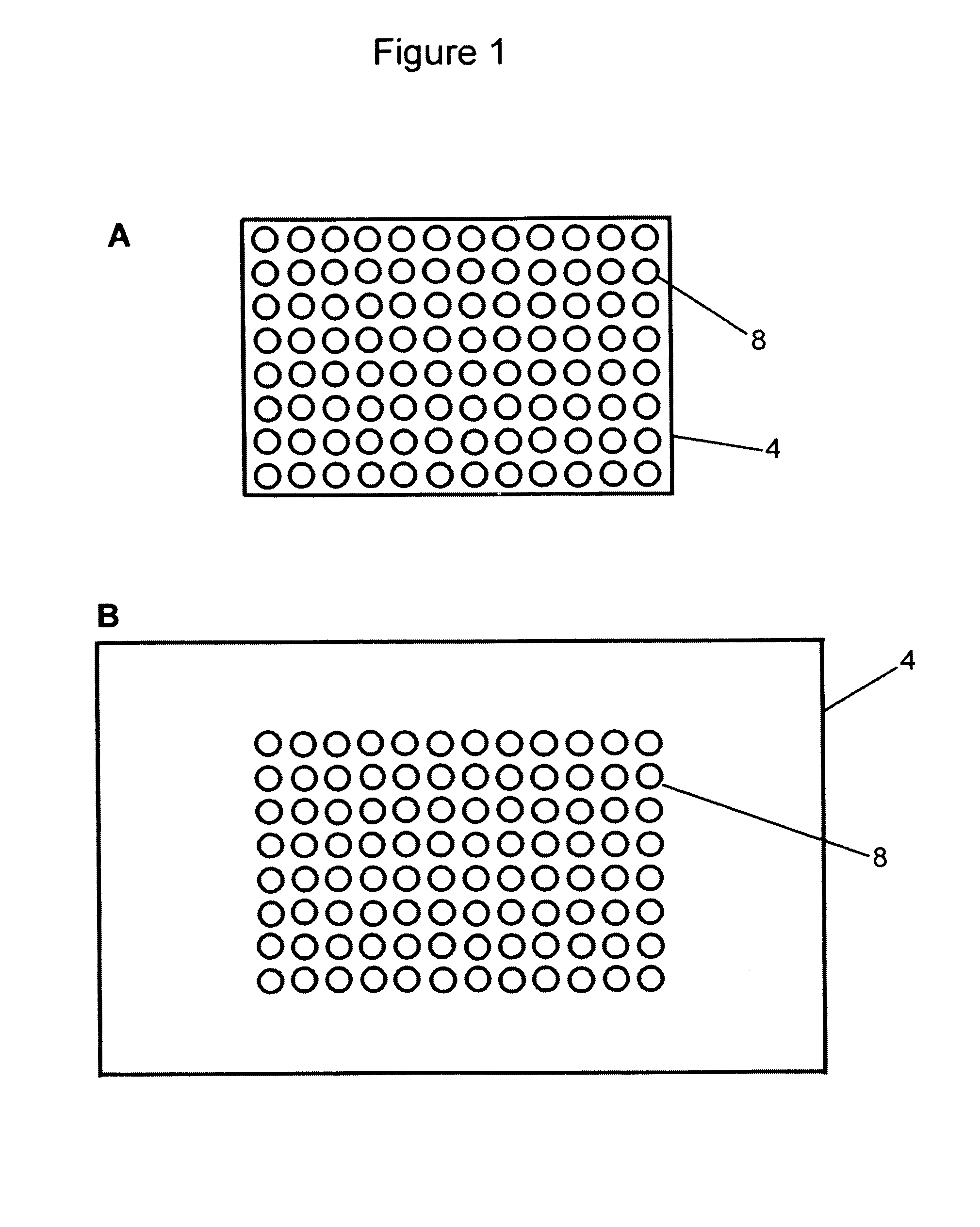
[0029]The present invention fulfills the need in the art for devices and methods that decrease the amount of time necessary to conduct cell-based screening, and specifically combines the ability to conduct high throughput and high content cell-based screening and to flexibly and rapidly switch from one to the other. The invention provides devices and methods for maximizing the number of wells that can be imaged at one time while still obtaining adequate pixel resolution in the image. This result has been achieved through the use of fluidic architectures that maximizes well density. The present invention thus provides a miniaturized microplate system with closed fluidic volumes that are internally supplied with fluid exchange, and with wells that are closely spaced to more rapidly detect spatially-resolved features of individual cells.
[0050]Among other uses, the devices and methods of the present invention are ideal for high content and / or high throughput cell-based screening. The device of the invention is also ideally suited as a cell support system for a hand-held diagnostic device (i.e.: a miniaturized imaging cell-based assay system). The smaller format and sealed containment of the present device enables its use in a rugged, portable system. There is a great economic advantage from the use of higher density plates. There is a further economic advantage in faster imaging of sub-arrays when using a high density plate; this advantage is not fully realized if the distances between adjacent wells are not minimized. The present invention provides both of these advantages.

Problems solved by technology

Traditionally, “lead compounds” have moved quickly to extensive animal studies that are both time-consuming and costly.
Furthermore, extensive drug testing in animals is becoming less culturally acceptable.
However, manipulation and analysis of drug-cell interactions using current methods does not allow for both high throughput and high biological content screening, due to the small number of cells and compounds that can be analyzed in a given period of time, the cumbersome methods required for compound delivery, and the large volumes of compounds required for testing.
The optical method of forming a micro-array of a single cell type on a support requires fewer steps and is faster than the photoresist method, (i.e., only two steps), but it requires the use of high intensity ultraviolet light from an expensive light source.
Such cell arrays are inflexible in their utility as tools for studying a specific variety of cells in a single sample or a specific variety of cell interactions.
For example, electrohydrodynamic pumping is less effective with polar solvents (Marc Madou, Fundamentals of Microfabrication, CRC Press, Boca Raton, 1997, p.
However, this device is not designed for use in cell based screening.
Finally, the '351 patent discloses a system of electrically-controlled electrohydrodynamic valves within the matrix of the wells that are less effective with aqueous media used in cell culture, and also may limit the degree of close-spacing between wells in the array of wells.
However, this patent does not disclose a substrate containing a cell array, nor an integrated fluidic device in combination with the substrate, nor a well density that is optimal for cell-based screening.
This patent does not teach a fluidic architecture that maximizes the area of the cell substrate that can be occupied by cell binding sites.
Nor does this patent disclose a substrate containing a cell array, nor an integrated fluidic device in combination with the substrate.
Furthermore, the patent only teaches the control of fluid flow by application of an electric field to the device.
Nor does the patent disclose a closed chamber to permit environmental control of the cells on the substrate.
Thus, none of these prior microfluidic devices provide a fluidic architecture that permits the closest possible well spacing (i.e.: highest possible well density), wherein the fluidic architecture is integrated with the cell array substrate to permit efficient fluid delivery to the cells, and thus eliminating the need for pipetting fluids in and out of wells.
Furthermore, prior microfluidic devices that comprise an array of wells use electrically-controlled electrohydrodynamic valves within the matrix of the wells that would be less effective if used with aqueous media for cell culture, and which limit the well density.
However, further increases in well density using prior technology are unlikely because of the great difficulty of pipetting liquids in and out of very small diameter wells.

Method used


Image

  • Miniaturized cell array methods and apparatus for cell-based screening
  • Miniaturized cell array methods and apparatus for cell-based screening
  • Miniaturized cell array methods and apparatus for cell-based screening

Examples


example 1

Coupling of Antibodies to Micro-Array of Multiple Cell Types for the Attachment of Specific Lymphoid Cells

[0171]1. The cell line used was a mouse B cell lymphoma line (A20) that does not express IgM on its surface. A micro-array of multiple cell types was prepared for derivatization by being immersed overnight in 20% sulfuric acid, washed 2–3 times in excess distilled water, rinsed in 0.1M sodium hydroxide and blotted dry. The micro-array of multiple cell types was either used immediately or placed in a clean glass beaker and covered with parafilm for future use.[0172]2. The micro-array of multiple cell types was placed in a 60 mm petri dish, and 3-Aminopropyltrimethoxysilane was layered onto the micro-array of multiple cell types ensuring complete coverage without running over the edges (approximately 0.2 ml for a 22×22 mm non-uniform micro-patterned array of cells, and approximately 0.5 ml for a 22×40 mm non-uniform micro-patterned array of cells). After 4 minutes at room temperat...

example 2

High-Content and High Throughput Screen

[0179]The insulin-dependent stimulation of glucose uptake into cells such as adipocytes and myocytes requires a complex orchestration of cytoplasmic processes that result in the translocation of GLUT4 glucose transporters from an intracellular compartment to the plasma membrane. A number of molecular events are triggered by insulin binding to its receptor, including direct signal transduction events and indirect processes such as the cytoskeletal reorganizations required for the translocation process. Because the actin-cytoskeleton plays an important role in cytoplasmic organization, intracellular signaling ions and molecules that regulate this living gel can also be considered as intermediates of GLUT4 translocation.

[0180]A two level screen for insulin mimetics is implemented as follows. Cells carrying a stable chimera of GLUT4 with a Blue Fluorescent Protein (BFP) are arranged on the micro-array of multiple cell types arrays, and then loaded ...

example 3

Improved Cassettes and Enhanced Well Density

[0182]In another aspect, the present invention provides devices and methods for maximizing the cell-plated area and the number of wells that can be imaged in a sub-array, while still obtaining adequate pixel resolution in the image. This result has been achieved through the use of fluidic architectures that minimize the distance and area between wells, thus maximizing well density.

[0183]In one embodiment of this aspect is provided a cassette for cell screening comprising a substrate having a surface, wherein the surface contains a plurality of cell binding locations; a fluid delivery system for delivering reagents to the plurality of cell binding locations, wherein the fluid delivery system comprises a multi-level chamber that mates with the substrate, wherein the multi-level chamber comprises[0184]i. a crossed array of microfluidic input channels and output channels, wherein each well is in fluid connection with one or more input channels...


PUM

PropertyMeasurementUnit
Volumeaaaaaaaaaa
Volumeaaaaaaaaaa
Volumeaaaaaaaaaa

Abstract

The present invention describes methods and cassettes for cell-based toxin detection and organ localization. The cassettes includes an array containing cells and a matrix of openings or depressions, wherein each region of the substrate enclosed by the opening or depression in the matrix forms a domain individually addressable by microfluidic channels in the device.

Description

RELATED APPLICATIONS[0001]This application claims priority to U.S. Provisional Patent Application Ser. Nos. 60 / 145,757 filed Jul. 27, 1999; is a continuation-in-part of U.S. patent application Ser. No. 09 / 540,862, filed Mar. 31, 2000, which is a continuation in part of U.S. patent application Ser. No. 09 / 401,212 filed Sep. 22, 1999; which is a continuation in part of 08 / 865,341 filed May 29, 1997, now U.S. Pat. No. 6,103,479; and is a continuation in part of U.S. patent application Ser. No. 09 / 513,783 filed Feb. 25, 2000, now U.S. Pat. No. 6,416,959.U.S. GOVERNMENT RIGHTS[0002]This invention was made in part with support from the U.S. Government under Contract No. N00014-98-C-0326, awarded by the U.S. Office of Naval Research, an organization of the U.S. Department of Defense. The U.S. Government may have certain nonexclusive rights in this invention.FIELD OF THE INVENTION[0003]The present invention relates to methods and devices for cell-based high throughput and high biological co...

Claims


Application Information

Patent Timeline
IPC IPC(8): G01N33/533
CPCB01L3/5027B82Y15/00B82Y30/00G01N33/5005G01N33/5014B01J2219/00317Y10S436/809B01J2219/00653B01J2219/00743B01L3/5025B01L3/50273B01L3/502738B01L7/00B01L2200/0668B01L2300/0864B01L2300/0867B01L2300/10B01L2400/0415B01L2400/0487G01N2800/52Y10S436/80B01J2219/00576
Inventor KAPUR, RAVIGIULIANO, KENNETH
Owner CELLOMICS
Learn More