
Attrition resistant bulk iron catalysts and processes for preparing and using same

a bulk iron catalyst, attrition resistant technology, applied in the field of iron catalysts, can solve the problems of catalyst fines produced by abrasion during use, difficulty in separation of liquid/wax product from the catalyst, and attrition is currently a major obstacle, so as to improve the attrition properties, reduce the attrition loss, and improve the effect of attrition

Inactive Publication Date: 2007-08-21
RES TRIANGLE INST +1
View PDF30 Cites 31 Cited by
  • Summary
  • Abstract
  • Description
  • Claims
  • Application Information

AI Technical Summary

Benefits of technology

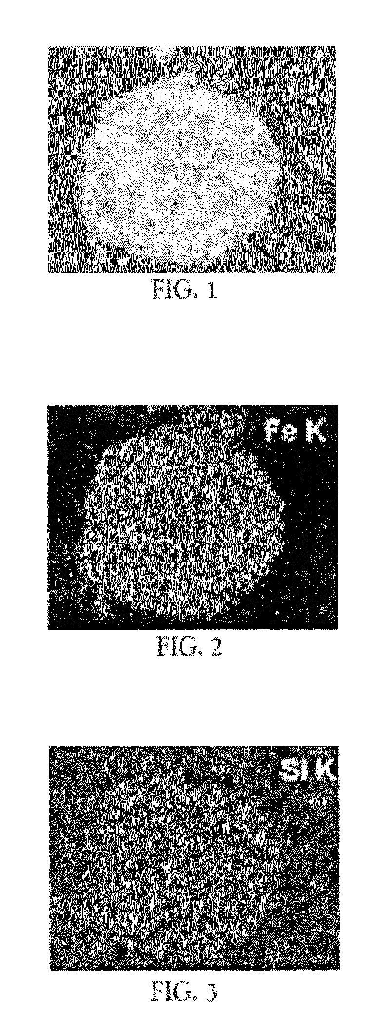
[0017]The attrition resistant bulk iron catalysts of the invention are substantially spherical particles comprising a finely divided iron component such as one or more iron oxides, typically Fe2O3, an iron oxide precursor, or an activated form of iron oxide, e.g., iron carbide or elemental iron (iron metal), and a substantially uniform distribution of binder, preferably silica. Advantageously, the iron component is present in an amount, calculated as Fe2O3, of at least about 50 wt. %, preferably at least about 60 wt. %, more preferably at least about 70 wt. %, most preferably about 80 wt. % or higher, based on adjusted catalyst weight (adjusted as necessary so that the iron component is calculated as Fe2O3). Advantageously, the catalysts of the invention also comprise an FTS promoter such as a copper and / or potassium FTS promoter, or a precursor thereof. Preferably, the binder content of the attrition resistant bulk iron catalysts of the invention is less than about 20 wt. %, more preferably between about 8 and about 16 wt. %. In preferred embodiments, the attrition resistant bulk iron catalysts of the invention have a bulk density exceeding 0.8 grams per cubic centimeter (g / cm3), more preferably, exceeding 0.8 grams per cubic centimeter g / cm3. Accordingly the bulk iron catalysts of the invention can be more readily separated from hydrocarbon products such as wax, compared to conventional precipitated bulk iron catalysts, which have a density of about 0.7 g / cm3, about the same as the density of wax.
[0019]In one preferred aspect of the invention, the slurry is treated with sufficient strong acid to reduce the pH to less than 2.0, preferably to about 1.0 to 1.5 prior to the spray drying step. A preferred strong acid is nitric acid. In accordance with this aspect of the invention, it has been found that reducing the slurry pH to below about 2.0, preferably to below about 1.5, before spray drying significantly improves the attrition properties, i.e., reduces the attrition loss, of the bulk iron catalyst of the invention.
[0020]The starting materials for the bulk iron catalyst of the invention are readily available in commerce. The catalyst of this invention has been found capable of providing FTS activity and selectivity that are much higher than supported iron catalysts reported in the prior art (for example, U.S. Pat. No. 5,928,980). The iron catalyst according to the present invention can be used because of its high attrition resistance in both calcined and carbided forms in virtually any reaction process including FTS, that uses a fluidized-bed reactor, or especially a slurry bubble column reactor.

Problems solved by technology

Catalyst attrition is currently a major obstacle to industrial application of precipitated bulk iron catalysts in a SBCR [Bhatt, et al.
The non-uniform particles and, especially, the irregular shapes of the catalyst particles produced by precipitation lead to production of catalyst fines by abrasion during use.
In turn, attrition of iron catalysts causes (i) plugging of filters, (ii) difficulty in separation of liquid / wax product from the catalyst, and (iii) steady loss of catalyst fines from the reactors.
Although the use of catalyst supports such as alumina (prepared as spheroids by spray drying) can improve catalyst attrition resistance, supported iron catalysts are generally limited to an iron oxide content of less than 30 wt.
This is because much less iron is available per unit weight of catalyst.
The supports also inhibit the activity of promoters and iron reduction and, thus, reduce catalyst effectiveness.
Improving the attrition properties of bulk iron catalysts is particularly difficult because bulk iron catalysts in a FTS SBCR are subject to both physical attrition and chemical attrition.
Chemical attrition can be caused during catalyst pretreatment and / or during FTS by iron catalyst phase changes (Fe2O3→Fe3O4→Fe metal and / or Fe carbide), resulting in a decrease or complete loss of physical integrity of the catalyst particles.
Although the role of these carbides in FTS is not resolved, the multiplicity of carbide phases and iron oxidation states can cause grain boundaries to grow during FTS which can place significant stresses on the iron particle that can lead to chemical attrition.
Past attempts to produce attrition-resistant, precipitated bulk iron FTS catalyst microspheres by spray drying have met with failure [Srinivasan et. al.
In fact, attrition was so severe for a spray dried, high α iron FTS catalyst prepared by United Catalysts, Inc. that a FTS pilot plant at Laporte, Tex. operated by Air Products for DOE had to shut down after only a few hours of testing due to production of catalyst fines and filter plugging [Private Communication with DOE, (1999)].
However, these catalysts are not said to be attrition resistant.
Thus, such catalyst would not suitable for a slurry-phase reactor from an attrition standpoint and, in addition, the catalysts particles in the lower portion of the 5 to 50 μm particle size range would be likely to plug filters through which wax is removed from the reactor.
Thus, despite substantial effort and research, there are no commercially available precipitated bulk iron FTS catalysts, which are attrition resistant and have substantial catalytic activity.
Accordingly, in practice, commercially available precipitated bulk iron catalysts, such as the standard Ruhrchemie pelletized catalyst, are supplied in pelletized form and are limited to use in fixed bed reactors.

Method used


Image

  • Attrition resistant bulk iron catalysts and processes for preparing and using same

Examples


example 1

[Catalyst 27]

[0062]This example describes the preparation and testing of the Catalyst 27 [100Fe / 5Cu / 4.2K containing 4% binder SiO2 by weight] of the invention. The preparation comprises the following steps: synthesis of catalyst precursor, spray drying of the catalyst precursor and calcination.

[0063]The catalyst precursor was prepared by co-precipitation at a constant pH of 6.2 using 1.0-M solution containing Fe (NO3)3.9H2O and Cu (NO3)32.5H2O in the desired Fe / Cu atomic ratio, which was precipitated by adding aqueous ammonium hydroxide solution. The resulting precipitate was then filtered and washed three times with deionized water. The potassium promoter was added as aqueous KHCO3 solution to the undried, reslurried Fe / Cu precipitate. This catalyst precursor was then slurried with polysilicic acid solution in a ratio to produce a final catalyst composition having 4 wt % SiO2. The pH of the slurry was 6.4 before spray drying. A 3 feet diameter×6 feet high Niro Inc. spray dryer was ...

example 2

[Catalyst 28]

[0065]This example describes the preparation and testing of the Catalyst 28 [100Fe / 5Cu / 4.2K containing 8% binder SiO2 by weight] of the invention. The preparation comprises the following steps: synthesis of catalyst precursor, spray drying of the catalyst precursor and calcination.

[0066]The catalyst precursor was prepared by co-precipitation at a constant pH of 6.2 using 1.0-M solution containing Fe (NO3)3.9H2O and Cu (NO3)32.5H2O in the desired Fe / Cu atomic ratio, which was precipitated by adding aqueous ammonium hydroxide solution. The resulting precipitate was then filtered and washed three times with deionized water. The potassium promoter was added as aqueous KHCO3 solution to the undried, reslurried Fe / Cu precipitate. This catalyst precursor was then slurried with polysilicic acid solution in a ratio to produce a final catalyst composition having 8 wt % SiO2. The pH of the slurry was 6.4 before spray drying. A 3 feet diameter×6 feet high Niro Inc. spray dryer was ...

example 3

[Catalyst 30]

[0068]This example describes the preparation and testing of the Catalyst 30 [100Fe / 5Cu / 4.2K containing 12% binder SiO2 by weight] of the invention. The preparation comprises the following steps: synthesis of catalyst precursor, spray drying of the catalyst precursor and calcination.

[0069]The catalyst precursor was prepared by co-precipitation at a constant pH of 6.2 using 1.0-M solution containing Fe (NO3)3.9H2O and Cu (NO3)32.5H2O in the desired Fe / Cu atomic ratio, which was precipitated by adding aqueous ammonium hydroxide solution. The resulting precipitate was then filtered and washed three times with deionized water. The potassium promoter was added as aqueous KHCO3 solution to the undried, reslurried Fe / Cu precipitate. This catalyst precursor was then slurried with polysilicic acid solution in a ratio to produce a final catalyst composition having 12 wt % SiO2. The pH of the slurry was 6.4 before spray drying. A 3 feet diameter×6 feet high Niro Inc. spray dryer wa...


PUM

PropertyMeasurementUnit
Timeaaaaaaaaaa
Densityaaaaaaaaaa
Fractionaaaaaaaaaa

Abstract

An attrition resistant precipitated bulk iron catalyst is prepared from iron oxide precursor and a binder by spray drying. The catalysts are preferably used in carbon monoxide hydrogenation processes such as Fischer-Tropsch synthesis. These catalysts are suitable for use in fluidized-bed reactors, transport reactors and, especially, slurry bubble column reactors.

Description

[0001]This invention was made with Government support under Contract No.: DE-FG22-96PC96217 awarded by the U.S. Department of Energy (DOE). The Government has certain rights in this invention.FIELD OF THE INVENTION[0002]This invention relates to iron catalysts for carbon monoxide hydrogenation processes such as Fischer-Tropsch synthesis. More specifically, the invention relates to bulk iron, i.e., high iron content, catalysts that are attrition-resistant, that can be used in slurry bubble column reactors, fluidized-bed reactors, and the like, and to processes for preparing and using these catalysts.BACKGROUND OF THE INVENTION[0003]Fischer-Tropsch synthesis (FTS) is a set of reactions by which CO and H2 (syngas) are converted into a wide variety of hydrocarbons [Dry, M. E., Catalysis-Science and Technology, p. 160, (1980); Anderson, R. B., et al., The Fischer-Tropsch synthesis, Academic Press, Inc., NY, (1984)]. This synthesis provides the best means currently available for the conve...

Claims


Application Information

Patent Timeline
IPC IPC(8): C07C1/00C01B3/12C07C27/00C22F3/00B01J21/08B01J23/745B01J23/78B01J27/22B01J35/00B01J35/10B01J37/00B01J37/03B01J37/08C01B3/16C10G2/00
CPCB01J23/745B01J23/78B01J35/002B01J37/0009B01J37/0045B01J37/08C01B3/16C10G2/332B01J21/08B01J27/22B01J35/0026B01J35/08B01J35/1014B01J35/1019B01J37/03C01B2203/0283C01B2203/1047Y02P20/52B01J35/31B01J35/30B01J35/51B01J35/613B01J35/615
Inventor JOTHIMURUGESAN, KANDASWAMYGOODWIN, JR., JAMES G.GANGWAL, SANTOSH K.
Owner RES TRIANGLE INST
Learn More