Laser system using ultrashort laser pulses

Active Publication Date: 2008-11-11
BOARD OF TRUSTEES OPERATING MICHIGAN STATE UNIV
View PDF89 Cites 67 Cited by
  • Summary
  • Abstract
  • Description
  • Claims
  • Application Information

AI Technical Summary

Benefits of technology

[0006]In accordance with the present invention, a laser system using ultrashort laser pulses is provided. In another aspect of the present invention, the system includes a laser, pulse shaper and detection device. A further aspect of the present invention employs a femtosecond laser and a spectrometer. Still another aspect of the present invention uses a laser beam pulse, a pulse shaper and a SHG crystal. In yet another aspect of the present invention, a multiphoton intrapulse interference phase scan (hereinafter “MIIPS”) system and method characterize the spectral phase of femtosecond laser pulses. In another aspect of the present invention, a system employs electromagnetic pulse shaping design to take advantage of multiphoton intrapulse interference. Fiber optic communication systems, photodynamic therapy and pulse characterization tests use the laser system with additional aspects of the present invention.
[0007]The laser system of the present invention is advantageous over conventional constructions since the MIIPS aspect of the present invention employs a single beam which is capable of retrieving the magnitude and sign of second and third order phase modulation directly, without iteration or inversion procedures. Thus, the MIIPS system is much easier to set up and use, thereby creating a much less expensive system which is more accurate than conventional systems and methods. Furthermore, the MIIPS system of the present invention avoids the inaccuracies of the prior FROG, SPIDER and DOSPM methods due to environmental effects such as wind, humidity and t

Problems solved by technology

Commercially practical femtosecond lasers have been unavailable until recently.
For example, lasers which can generate 10 femtosecond or less laser pulse durations have traditionally been extremely expensive, required unrealistically high electrical energy consumption (for extensive cooling, by way of example) and depended on laser dyes that had to be replenished every month thereby leading to commercial impracticality.
The efficiency of sub-10 femtosecond lasers was not practical until the year 2000 because of the prior need for dyes and flash lamps instead of YAG and Ti: Sapphire crystals pumped by light or laser emitting diodes.
Ultrashort pulses are prone to suffer phase dis

Method used


Image

  • Laser system using ultrashort laser pulses
  • Laser system using ultrashort laser pulses
  • Laser system using ultrashort laser pulses

Examples


example 1

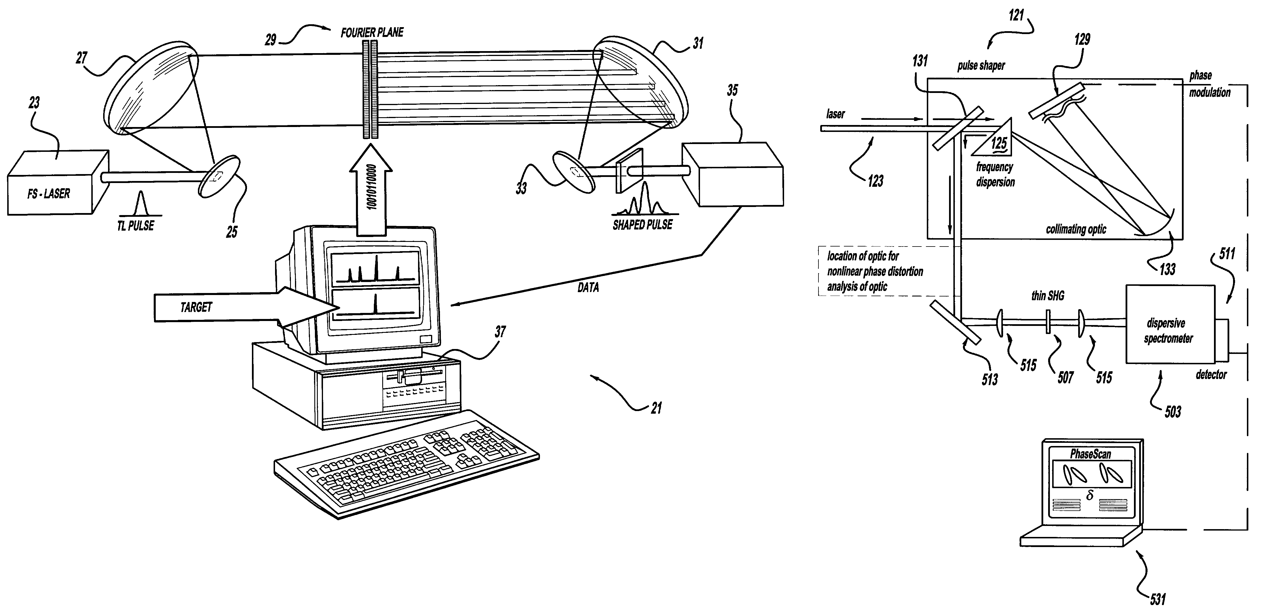
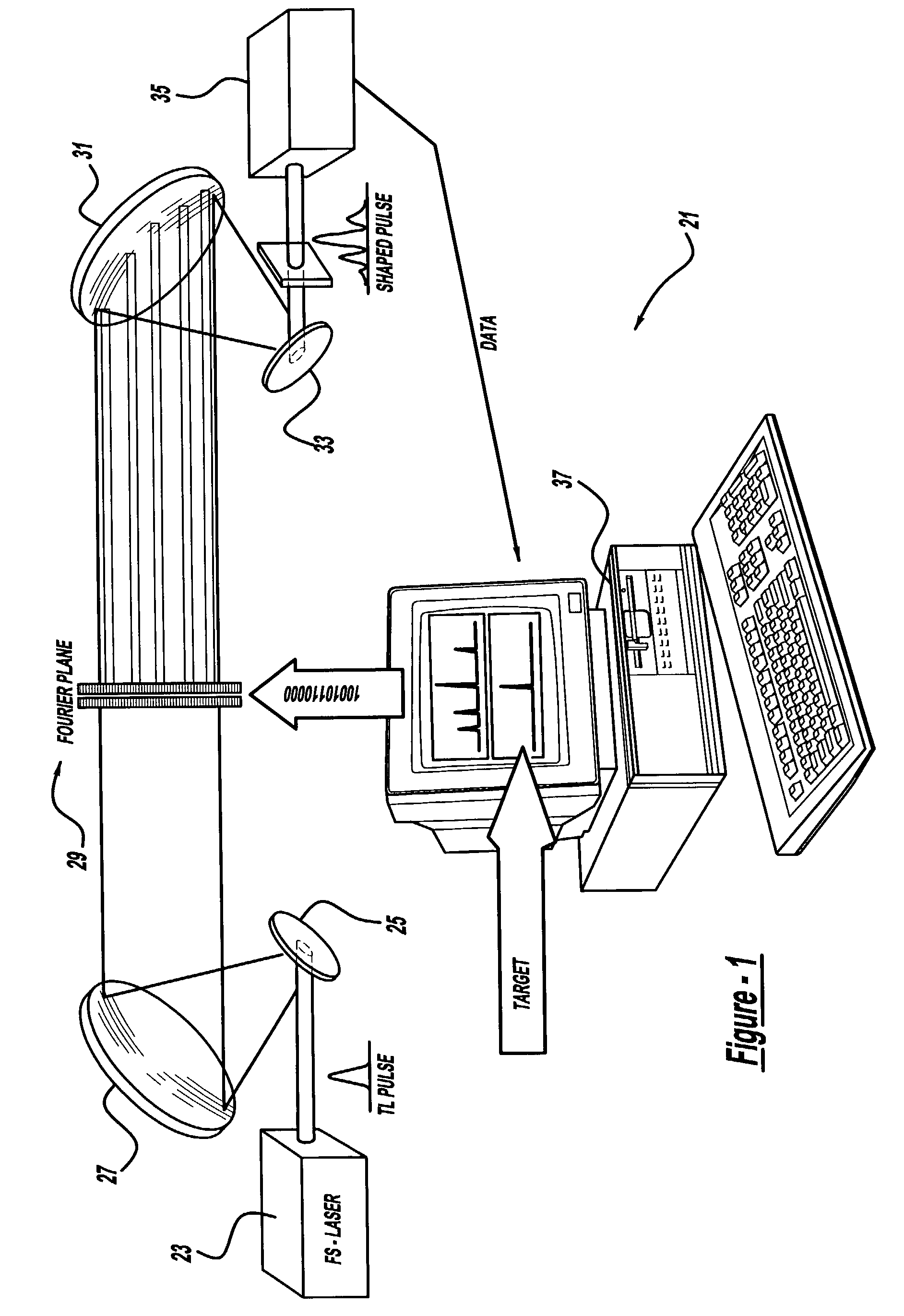
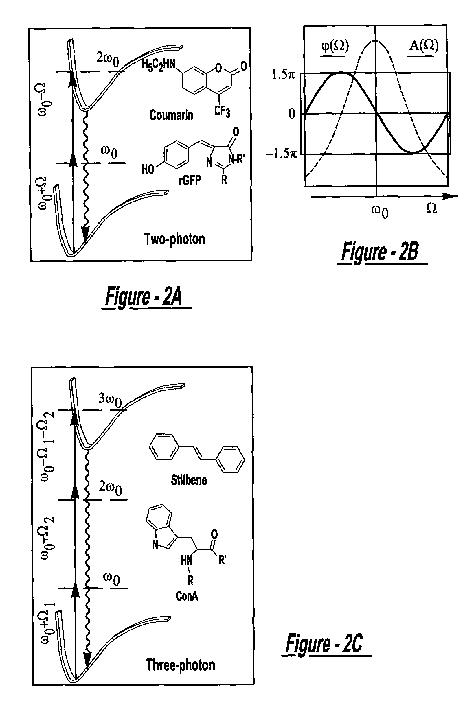
[0048]The experiments in all of the following examples were carried out using an amplified titanium sapphire laser producing 50 fs pulses. The pulses were shaped using a spatial light modulator (hereinafter “SLM”) at the Fourier plane of a zero-dispersion two grating arrangement. The two independent modulator plates, based on liquid crystal technology in the SLM (128 pixels each), were calibrated so that only phase delays were introduced without changes to the output spectrum, intensity, and polarization. The shaped pulses centered at 809 nm were characterized by second harmonic generation frequency resolved optical gating. When all phases were set to zero, laser pulses were near transform limited. Unless indicated otherwise, measurements were made with pulse energies of 0.4 μJ / pulse at the sample. Experiments were carried out by setting the phase function equal to a sinusoid, as shown in FIG. 2B, in the 779-839 nm spectral range. Emission from one photon or multiphoton induced proc...

example 2

[0052]Experimental results for various samples obtained with a full-period sinusoidal phase mask are shown in FIGS. 4A-4G. FIG. 4A shows one photon laser induced fluorescence (hereinafter “1PLIF”) of IR144 observed at 842 nm as a function of phase mask position. This measurement was made with 0.3 nJ / pulse to avoid nonlinear processes at the specimen. It is noteworthy that one photon process in the weak field regime show no dependence on phase shaping. FIG. 4B shows results for the two photon laser induced fluorescence (hereinafter “2PLIF”) from Coumarin collected at 500 nm. The data in FIG. 4C shows the dependence of 2PLIF in recombinant green fluorescent protein (hereinafter “rGFP”) detected at 505 nm. The data in FIG. 4D corresponds to the intensity of the second harmonic generation (hereinafter “SHG”) signal at 405 nm from a 0.3 mm β-barium borate crystal. The maximum and minimum signal for SHG coincides with that observed for 2PLIF but is not identical.

[0053]With reference to FI...

example 3

[0055]FIG. 5A presents the maximum discrimination between linear and nonlinear response observed for intense pulses (0.5 μJ / pulse). Separate detectors simultaneously collected the 1PLIF from IR144 solution and a portion of the continuum output. Maximum and minimum contrast ratios of >103:1 and 1:0.6 were obtained for one photon process versus continuum, respectively, as shown in FIGS. 5A and 5B. This control is extremely valuable when one is interested in linear processes under high-flux conditions, like in laser microscopy or in optical fiber communications. Using the simple phase function discussed earlier, particular windows of opportunity to control second versus higher order processes can be employed as demonstrated in FIGS. 5C and 5D. For certain values of δ, continuum generation even for relatively high intensity laser pulses (˜1 μJ / pulse) can be completely suppressed. FIGS. 5C and 5D show that maximum and minimum contrast ratios of >103:1 and 1:4 were obtained for 2PLIF vers...


PUM


Abstract

A laser system using ultrashort laser pulses is provided. In another aspect of the present invention, the system includes a laser, pulse shaper and detection device. A further aspect of the present invention employs a femtosecond laser and a spectrometer. Still another aspect of the present invention uses a laser beam pulse, a pulse shaper and a SHG crystal. In yet another aspect of the present invention, a multiphoton intrapulse interference phase scan system and method characterize the spectral phase of femtosecond laser pulses. Fiber optic communication systems, photodynamic therapy and pulse characterization tests use the laser system with additional aspects of the present invention.

Description

CROSS REFERENCE TO RELATED APPLICATIONS[0001]This is a continuation-in-part of PCT / US02 / 02548, filed Jan. 28, 2002 claiming priority to U.S. provisional application Ser. No. 60 / 265,133, filed Jan. 30, 2001, which are incorporated by reference herein.BACKGROUND AND SUMMARY OF THE INVENTION[0002]The present invention generally relates to a laser system and more particularly to a laser system using ultrashort laser pulses with phase modulation.[0003]Commercially practical femtosecond lasers have been unavailable until recently. For example, lasers which can generate 10 femtosecond or less laser pulse durations have traditionally been extremely expensive, required unrealistically high electrical energy consumption (for extensive cooling, by way of example) and depended on laser dyes that had to be replenished every month thereby leading to commercial impracticality. The efficiency of sub-10 femtosecond lasers was not practical until the year 2000 because of the prior need for dyes and f...

Claims


Application Information

Patent Timeline
IPC IPC(8): H01S3/10G01B9/02H01J49/16H01S3/00
CPCG01B9/02014H01S3/0057G01B9/02044G01B9/02091G01N21/6402A61B5/0066A61B5/0073A61N5/062
Inventor DANTUS, MARCOSLOZOVOY, VADIM V.
Owner BOARD OF TRUSTEES OPERATING MICHIGAN STATE UNIV
Why Eureka
Try Eureka