

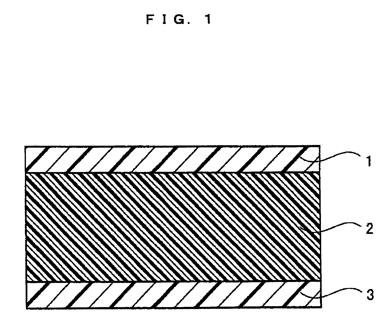
Composite ion-exchange membrane
a technology of ion exchange membrane and composite ion, which is applied in the direction of cell components, non-aqueous electrolyte cells, electrochemical generators, etc., can solve the problems of difficult control of sulfonation reactions by this method, inability to adjust the degree of sulfonation to a desired degree, and limited operation temperature of fuel cells using such membranes, etc., to achieve superior mechanical strength and ion conductivity, and high swelling resistan
- Summary
- Abstract
- Description
- Claims
- Application Information
AI Technical Summary
Benefits of technology
Problems solved by technology
Method used
Image

Examples
synthesis example 1
(i) Synthesis Example 1
[0279]First, 12.28 g (25.0 mmol) of sodium 4,4′-dichlorodiphenylsulphone-3,3′-disulfonate, 7.18 g (25.0 mmol) of 4,4′-chlorodiphenylsulfone, 9.31 g (50.0 mmol) of 4,4′-biphenol, 7.95 g (57.5 mmol) of potassium carbonate, 100 ml of N-methyl-2-pyrrolidone and 15 ml of toluene were charged into a 200 ml side-arm flask equipped with a nitrogen introduction tube, a stirring blade, a Dean-Stark trap and a thermometer and then were heated under nitrogen flow while being stirred on an oil bath.
[0280]Subsequently, after dehydration by azeotropy with toluene was conducted at 140° C., toluene was removed completely by distillation. Thereafter the temperature was raised to 200° C. and heating was continued for 15 hours. Subsequently, the solution cooled to room temperature was poured into 2000 ml of pure water. Thus, ion exchange resin was reprecipitated. Then, the ion exchange resin filtered was dried under reduced pressure at 50° C. to yield the ion exchange resin of Sy...
synthesis examples 2 to 12
(ii) Synthesis Examples 2 to 12
[0281]The ion exchange resins of Synthesis Examples 2 to 12 were synthesized in the same manner as Example 1, with the exception that the kinds and molar ratios of monomers were changed as shown in Table 1. The yields and the measurements of inherent viscosity of the ion exchange resin are also shown in Table 1.
[0282]
TABLE 1Charge amount of monomer (mmol)InherentS-YieldviscosityDCDPSDCBNDCDPSBPBPF(%)(dl / g)Synthesis25—2550—950.95Example 1Synthesis30—2050—930.83Example 2Synthesis35—1550—900.77Example 3Synthesis25—25—50910.54Example 4Synthesis35—15—50890.53Example 5Synthesis40—10—50850.59Example 6Synthesis2030—50—930.88Example 7Synthesis2525—50—910.91Example 8Synthesis3020—50—840.79Example 9Synthesis15—3550—970.94Example 10Synthesis18—32—50980.55Example 11Synthesis133750—960.91Example 12S-DCDPS: sodium 4,4′-dichlorodiphenylsulfone-3,3′-disulfonateDCBN: 2,6-dichlorobenzonitrileDCDPS: 4,4′-dichlorodiphenylsulfoneBP: 4,4′-biphenolBPF: 9,9-bis(4-hydroxyphenyl...
example 1
[0284]First, an isotropic solution with a poly(p-phenylene-cis-benzobisoxazole) concentration of 1% by mass was prepared by diluting a dope comprising polyphosphoric acid containing 14% by mass of poly(p-phenylene-cis-benzobisoxazole) polymer having an intrinsic viscosity of 25 dL / g by addition of methane sulfonic acid.
[0285]Then, this solution was formed into a film on a glass plate heated to 90° C. at a film formation rate of 5 mm / sec using an applicator with a clearance of 300 μm. The dope film formed on the glass plate was placed as it was in a thermohygrostat at 25° C. and 80% RH and was solidified for one hour. The resulting film was washed with water until the washings exhibited pH 7±0.5, yielding a support membrane.
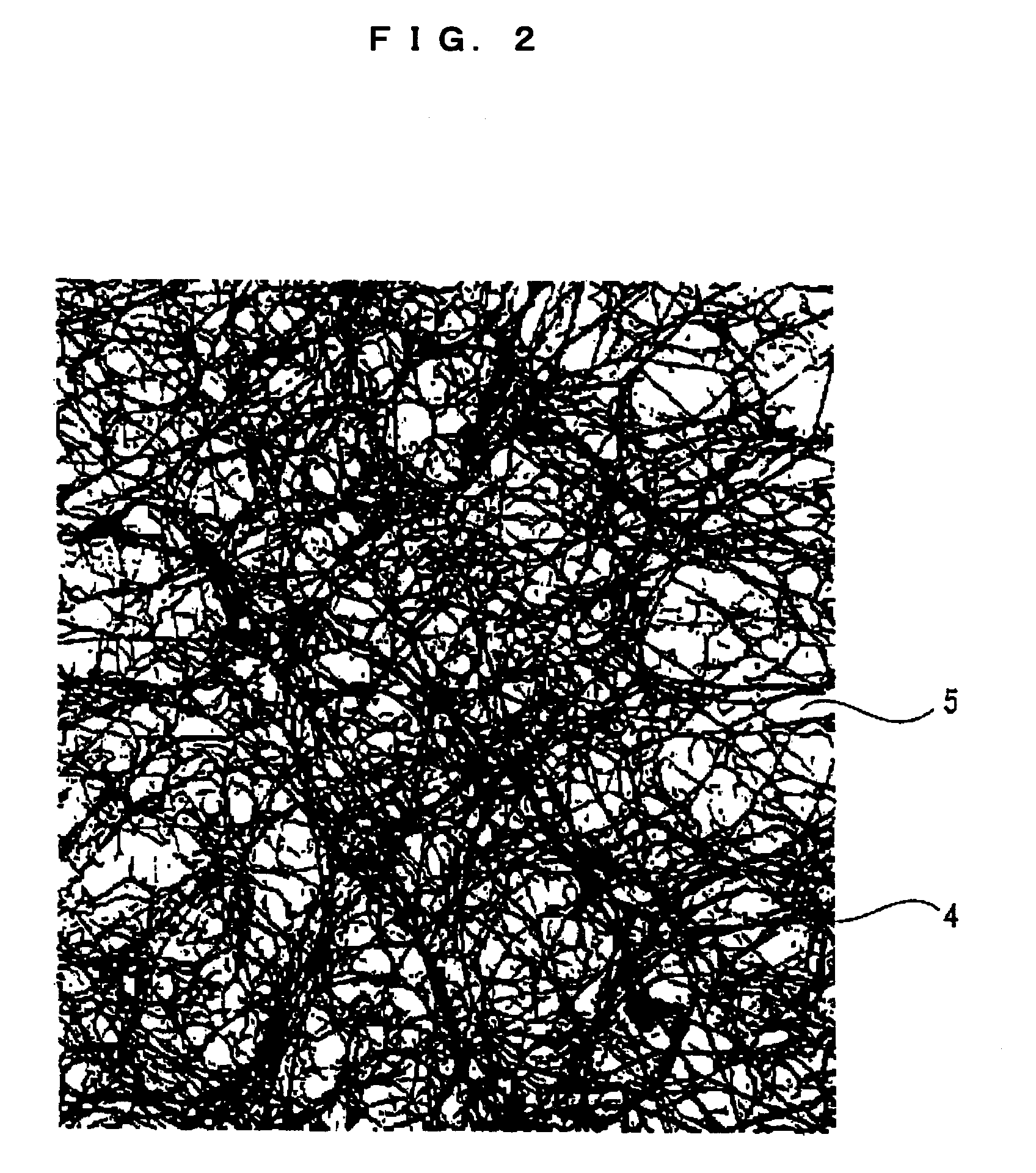
[0286]Subsequently, the surface morphology observation by an atomic force microscope and the section morphology observation by a transmission electron microscope of the resulting support membrane confirmed that the membrane was a porous membrane with continuous po...
PUM
| Property | Measurement | Unit |
|---|---|---|
| total thickness | aaaaa | aaaaa |
| porosity | aaaaa | aaaaa |
| operating temperature | aaaaa | aaaaa |
Abstract
Description
Claims
Application Information