Laminated optical element

a technology glass, which is applied in the field of laminated optical elements, can solve the problems of high production high heat resistance of expensive molding dies, and high cost of glass optical elements, and achieves high hardness, good adhesion, and high reliability.

Inactive Publication Date: 2011-02-15
SANYO ELECTRIC CO LTD
View PDF13 Cites 6 Cited by
  • Summary
  • Abstract
  • Description
  • Claims
  • Application Information

AI Technical Summary

Benefits of technology

[0112]The laminated optical element according to the present invention has an intermediate layer obtained by dispersing metal oxide microparticles in a matrix resin composed of a metal alkoxide and / or a hydrolysate thereof having a radical polymerizable group and a hydrolyzable group, and the intermediate layer is provided between an optical substrate and an optical resin layer so that the optical resin layer can have good adhesion to the optical substrate. Therefore, the laminated optical element according to the present invention has high reliability under high temperature and high humidity conditions and has high hardness and high heat resistance.

Problems solved by technology

However, in order to obtain glass optical elements having an aspherical surface other than a flat or spherical surface, it is necessary to use a special grinding machine or to mold a glass material, which can be molded at low temperature, with an expensive molding die having high heat resistance (e.g., a ceramic molding die).
Therefore, the production cost of such a glass optical element is high and the resulting glass optical element is very expensive.
However, such optical elements have a problem in that they have low heat resistance, high thermal expansion, narrow range of choices in their optical properties such as refractive index, and low reliability.
However, such a laminated optical element involves a problem that it is difficult for the optical resin layer to keep good adhesion to the substrate under severe conditions and therefore the separation of the optical resin layer is likely to occur.
The problem of separation of the optical resin layer can be solved by increasing the silane coupling agent content of the silane coupling agent coating, but this method causes another problem that the surface of the silane coupling agent coating becomes clouded or the silane coupling agent cannot be coated on the substrate evenly, that is, uneven coating occurs.
However, in a case where a high refractive index glass whose silica (SiO2) content is low is used as a glass substrate, adhesion between the glass substrate and the optical resin layer cannot be improved by the silane coupling agent.
However, the dielectric multilayer film is formed by vacuum evaporation, ion plating, or sputtering, which makes it difficult to produce such an optical element at low cost in a short time.

Method used


Image

  • Laminated optical element
  • Laminated optical element
  • Laminated optical element

Examples


example 1

[0209]

[0210]A hybrid aspherical lens was produced through the steps shown in FIGS. 11(a) to 11(e).

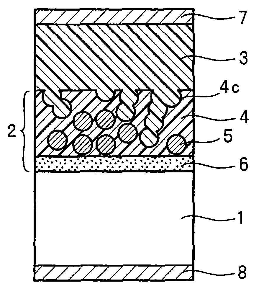
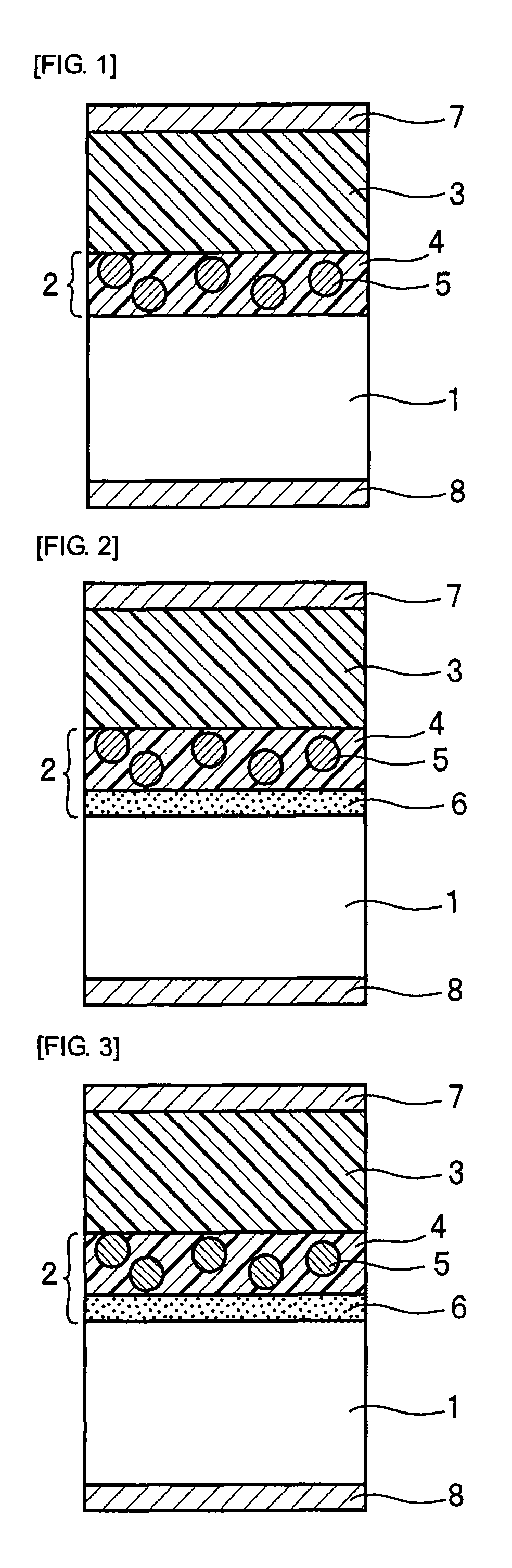
[0211]As shown in FIG. 11(a), a spherical lens made of glass was used as an optical substrate 1, and an intermediate layer 2 was formed on the optical substrate 1. Onto the intermediate layer 2, the optical resin layer-forming solution 3 was dropped. As the optical substrate 1, a high refractive index spherical glass lens having a diameter of 5 mm and a maximum thickness of 1 mm (refractive index of glass nD: about 1.8) was used. The intermediate layer 2 was formed by heating the silicon oxide particle dispersion liquid spin-coated on the optical substrate 1 at 100° C. for 1 hour.

[0212]As shown in FIG. 11(b), a nickel mold 10 having an aspherical inner surface was pressed against the optical resin layer-forming solution 3, and then, as shown in FIG. 11(c), the optical resin layer-forming solution 3 was cured by irradiation with ultraviolet rays from the optical substrate 1 side to form ...

example 2

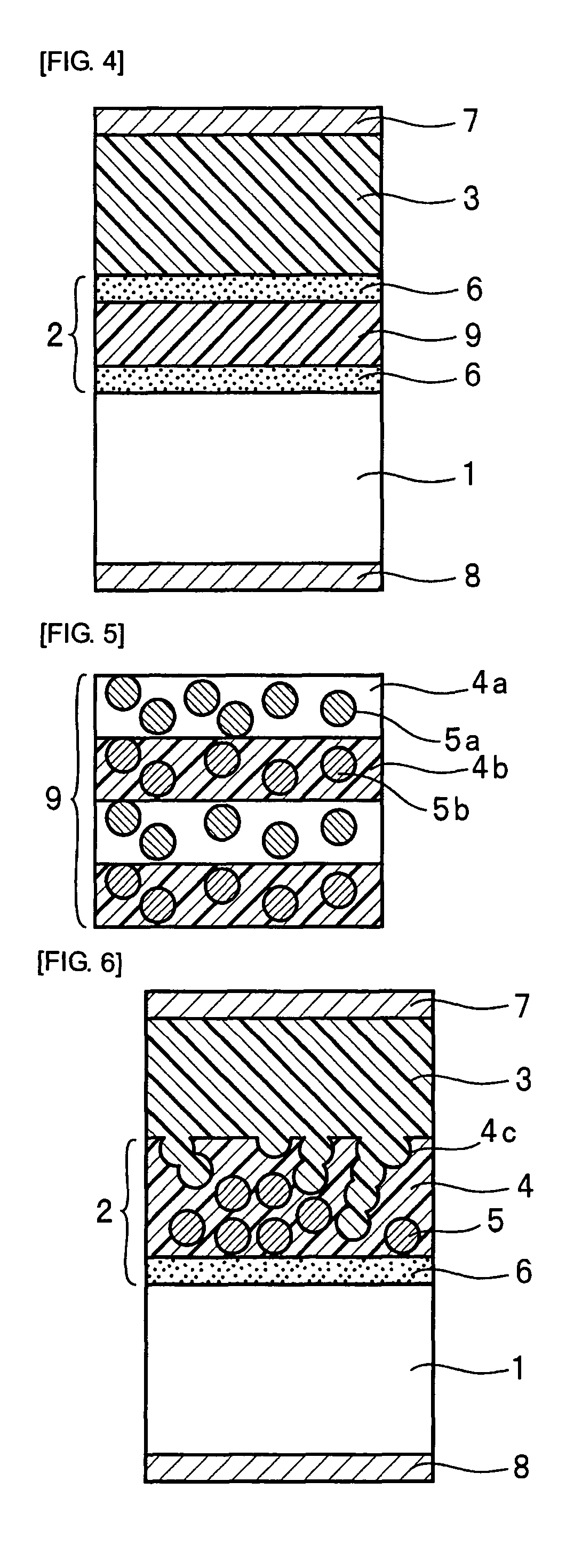
[0217]As shown in FIG. 2, a hybrid aspherical lens was produced in the same manner as in the Example 1 except that the intermediate layer 2 was replaced with one comprising a coupling agent layer 6 provided on the optical substrate 1 and a matrix resin layer 4, containing silicon oxide particles 5 dispersed therein, provided on the coupling agent layer 6.

[0218]The coupling agent layer 6 was formed by heating the coupling agent solution 3 spin-coated on the optical substrate 1 at 140° C. for 1 hour. The thickness of the coupling agent layer 6 is 10 nm. The matrix resin layer 4 was formed in the same manner as in the Example 1. The maximum thickness of the matrix resin layer 4 is 200 nm.

[0219]Therefore, the thickness of the intermediate layer 2 of Example 2 is 210 nm.

example 3

[0220]In this example, niobium oxide particles were used as microparticles 5. More specifically, a hybrid aspherical lens was produced in the same manner as in the Example 2 except that the matrix resin layer 4 was replaced with one formed using the niobium oxide particle dispersion liquid containing niobium oxide particles as microparticles 5.


PUM

PropertyMeasurementUnit
particle sizeaaaaaaaaaa
thicknessaaaaaaaaaa
humidityaaaaaaaaaa

Abstract

A laminated optical element includes an optical substrate made of an optical material, an intermediate layer provided on the optical substrate, and an optical resin layer provided on the intermediate layer. The optical resin layer is made of a resin composed of an organometallic polymer having an -M-O-M- bond (M is a metal atom), a metal alkoxide and / or a hydrolysate thereof having only one hydrolyzable group, and an organic polymer having a urethane bond and a methacryloxy group or an acryloxy group. The intermediate layer is obtained by dispersing metal oxide microparticles in a matrix resin composed of a metal alkoxide having a radical polymerizable group and a hydrolyzable group and / or a hydrolysate thereof.

Description

TECHNICAL FIELD[0001]The present invention relates to a laminated optical element useful for electric wiring boards, machine part materials, various coatings such as an antireflection coating and a surface protection coating, optical communication devices such as an optical transmitter and receiver module, an optical switch, and an optical modulator, optical devices such as an optical propagation path structure (e.g., an optical waveguide, an optical fiber, and a lens array) and an optical beam splitter having such an optical propagation path structure, monitor (display or liquid crystal projector)-related optical devices such as an integrator lens, a microlens array, a reflector plate, a light guide plate, and a projection screen, eyeglasses, CCD optical systems, lenses, hybrid aspherical lenses, 2P (Photoreplication Process) lenses, optical filters, diffraction gratings, interferometers, optical couplers, optical branching filters, optical sensors, hologram optical elements, other...

Claims


Application Information

Patent Timeline
Patent Type & Authority Patents(United States)
IPC IPC(8): B32B5/16
CPCB32B5/16G02B3/02Y10T428/25Y10T428/24413Y10T428/265G02B3/00G02B5/188G02B5/1895Y10T428/31598Y10T428/31609
Inventor KURAMOTO, KEIICHIHAYASHI, NOBUHIKOHIRANO, HITOSHIMATSUMOTO, MITSUAKINAKAI, MASAYA
Owner SANYO ELECTRIC CO LTD
Why Eureka
Try Eureka