[0013]The present invention affords a method and apparatus for suppression of CCI via the use of receive antenna arrays at the BS for the
uplink channel. In addition, those skilled in the art will recognize that the application of this invention is not limited to the BS
uplink channel, but is also applicable elsewhere including the BS downlink and at the remote
transmitter / receivers. The intelligent use of antenna arrays for mitigating fading and interference is also referred to as “smart” or “intelligent antennas”.
Smart antenna systems may be carried out through the use of switched beam antennas or adaptive arrays (AA). Switched beam antennas use a fixed
beamforming network to provide several output ports corresponding to beams in fixed directions.
Signal levels in each beam are monitored and analyzed to switch the beams appropriately among different time or frequency channels depending on the air-interface scheme. Adaptive arrays, on the other hand, electronically steer a
phased array by weighting the amplitude and phase of signal at each element in response to changes in the propagation environment. Adaptive arrays provide greater steering flexibility in response to the propagation environment. The preferred embodiment focuses on adaptive arrays. However, switched beam antennas may be used.
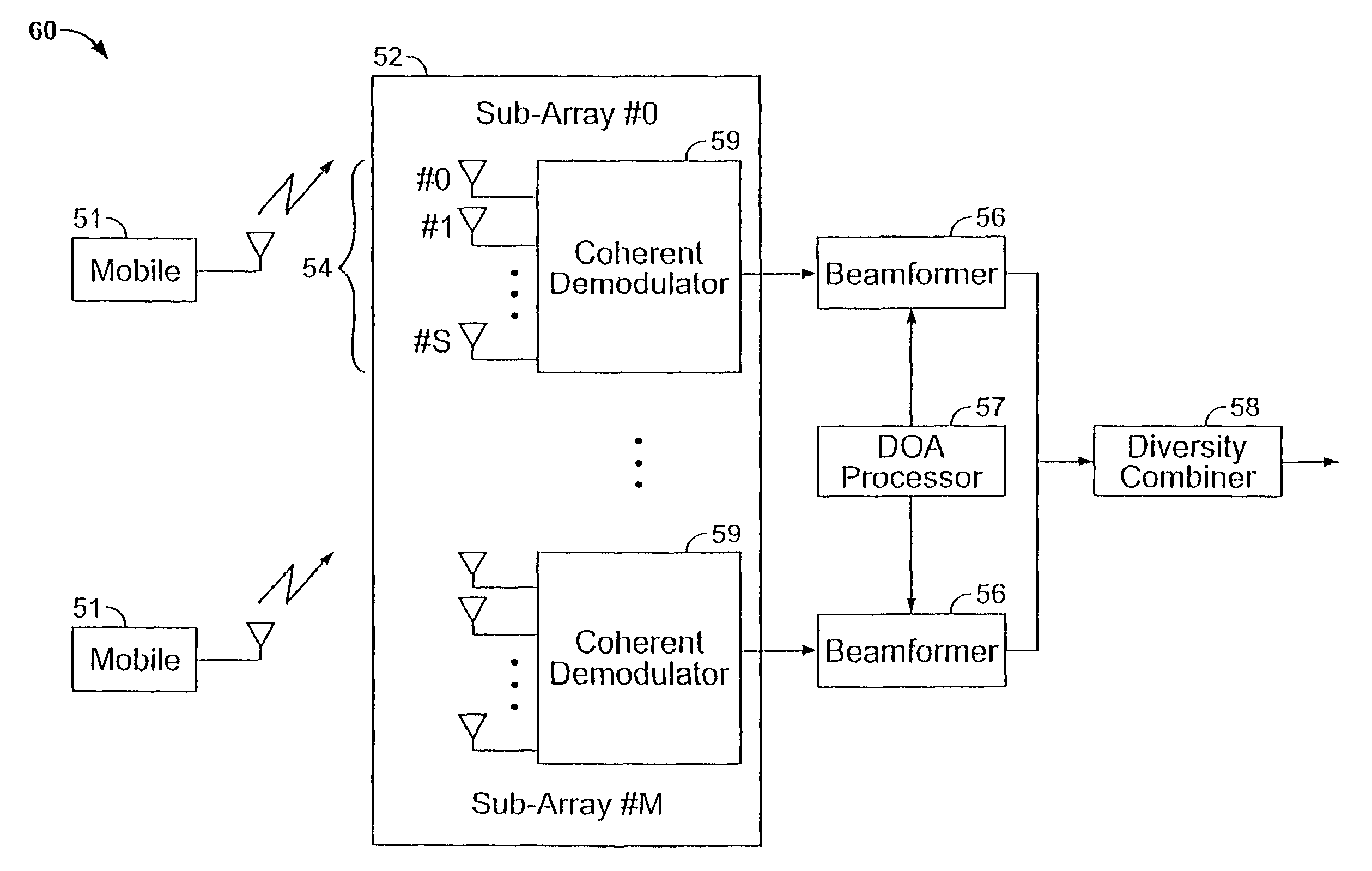
[0020]First, the
antenna array is partitioned into sub-arrays. The elements of each sub-array are spaced close together (e.g., half
wavelength or less to avoid spatial
aliasing or
grating lobes) to facilitate beamforming. Second, the individual sub-arrays are spaced far apart (e.g., 5-15 wavelengths) to obtain spatial diversity. The preferred embodiment uses each sub-array for beamforming for CCI suppression. Since the post-beamforming outputs from each sub-array may be largely affected by
noise only, they can be diversity combined.
Diversity combining can be done using MRC (which requires channel
estimation). But channel
estimation is expected to be easier in the second stage since the first stage is expected to greatly reduce the interference. No FEQ is required since the MRC essentially serves the role of a “multi-element” FEQ. If MRC is not feasible,
switched diversity combining (SDC) may be used by measuring the instantaneous SNR for each sub-array's output and selecting the “best” option each symbol time (other variations are also possible). In this case, a standard FEQ is still required. As mentioned earlier, techniques for channel
estimation via time-frequency patterns of pilots can be used in conjunction with the proposed AA architecture and an overall improvement in performance and / or reduction in complexity / bandwidth overhead of those algorithms is expected. Note that the use of this two-stage architecture and method is not limited to operation over FFC only and can be used over SFC as well instead of MSOC (but MSOC is very difficult to implement over FFC). Thus, the two-stage method can be considered to be more general. Nor is the number of elements in each sub-array or the number of sub-arrays limited. Increasing the number of elements in each sub-array can provide for more-optimal beamforming while increasing the number of sub-arrays outputs that are diversity combined can serve to further reduce interference. As an example, a preferred embodiment may have each sub-array made up of 4-8 elements with 2 sub-arrays for a total of 8-16 elements.
[0022]A number of methods may be used for DOA estimation. For example, some remote transmitters may be equipped with GPS type equipment to enable the BS to compute this information. Other possible methods are the use of BS
triangulation via time-difference-of-arrival (TDOA) measurements. One method to estimate DOA's of a given user is by using adjacent
antenna array elements in each sub-array. The idea here is to extract the phase differences between complex
baseband (
symbol rate) samples from adjacent sensors or doublets. As mentioned above, the sensors in each sub-array are spaced a half-
wavelength apart or closer to avoid spatial
aliasing. For a range of channel scenarios, the fading experienced by adjacent sensors is almost perfectly correlated. For the range of signal bandwidths and RF carrier frequencies, the signals can be considered to be
narrowband. Thus, when the signals are coherently downconverted and demodulated, a mutual
phase offset is induced between the samples obtained from adjacent sensors. This
phase offset is proportional to the inter-sensor spacing (normalized in wavelengths) and the sine of the DOA measured with respect to the normal to the array. This spatially induced
phase offset is not only obtained for successive symbols, but also for all bins being used by a particular user. Thus, the measured phase offset can be smoothed in space (over multiple doublets in each sub-array and using multiple sub-arrays), in time (over a block of symbols), and in frequency (over multiple bins used by the same user) to mitigate the effect of
noise. Note that since all
array processing algorithms operate on complex
baseband outputs, the
processing can be efficiently done in the
frequency domain. Also note that the AA
receiver structures may also be implemented in conjunction with sectorized cells. For example, each
cell can have 3-6 sectors and an AA
receiver can be used within each sector. Of course, one of the advantages of AA in cellular / PCS systems is to achieve a reduction in the number of sectors per
cell (which will improve the
trunking efficiency) and still derive benefits of spatial separation between signals.
[0026]1. The K bins belonging to any one user should be spaced as far apart in frequency as possible to minimize mutual IBI. Spacing the bins belonging to each user over a wide range of frequencies within the band also provides frequency diversity. Frequency diversity is desirable because it serves to lessen the effects of fading over a certain frequency range. For example, by allocating many widely spaced frequency bins to a single user, if the
operating environment is such that some of the bins experience fading, the overall
signal quality will still remain high because the other user bins will not experience this fading; in short, fading over a small frequency range within the band will not effect the whole signal.
[0028]3. Each bin is placed in a neighborhood with bins belonging to other users such that differences in
signal strength of active bins in the neighborhood are minimized.

