Random texture anti-reflection optical surface treatment

Active Publication Date: 2012-05-29
COHO HLDG
View PDF13 Cites 137 Cited by
  • Summary
  • Abstract
  • Description
  • Claims
  • Application Information

AI Technical Summary

Benefits of technology

[0028]In another application, the present invention provides a process for producing surface relief microstructures with a random distribution over the surface of large area glass or plastic windows that in combination with titania or other material coatings, may be useful for the inexpensive production of hydrogen split from water using sunlight.
[0029]In still another application, the present invention provides an AR treatment for infrared

Problems solved by technology

Light reflecting from instrument panel and center console automobile displays is distracting to drivers and necessitates overhanging dashboard designs that take up valuable interior space.
The glare of unwanted reflected light from mobile phone and automobile instrument panels is an even more severe problem due to the addition of plastic cover windows that are designed to protect the display from damage due to constant handling or cleaning.
With prescription eyeglasses, reflected light produces overlapping images that hamper the wearer's vision significantly.
In particular, reflections from car headlights are a severe problem for eyeglass wearers driving at night.
Sunglass wearers have a similar problem during the day where reflections from the lens surface nearest the eye create a distracting image of the wearer's own eye.
In addition, reflected light off the front or external lens surface decreases the amount of light transmitted to the eye and thus decreases the optical quality of the lens noticeable to the wearer.
This external reflection also produces an annoying shine or glare to an observer of the person wearing the eyeglasses.
Glare or glint and decreased light transmission become severe in other optical systems that have multiple reflective surfaces such as the compound lenses found in cameras, microscopes and telescopes.
Reflected light is a major problem in military, industrial, space and commercial applications that employ infrared (IR) light.
The problem gets worse for IR light incident at higher angles off the normal to the window.
Such large reflections produce stray light and can lead to superimposed images that can reduce the contrast or even blind security cameras or the night imaging systems found on aircraft, ground equipment, and satellites.
In addition, the performance of thin-film AR coatings is limited to applications where light is incident along or near the

Method used


Image

  • Random texture anti-reflection optical surface treatment
  • Random texture anti-reflection optical surface treatment
  • Random texture anti-reflection optical surface treatment

Examples


Example

[0061]The foregoing and other objects features and advantages of the invention will be apparent from the following more particular description of preferred embodiments of the invention, as illustrated in the accompanying drawings in which like reference characters refer to the same parts throughout the different views. The drawings are not necessarily to scale, emphasis instead being placed upon illustrating the principles of the invention.

DETAILED DESCRIPTION OF THE INVENTION

[0062]A description of preferred embodiments of the invention follows.

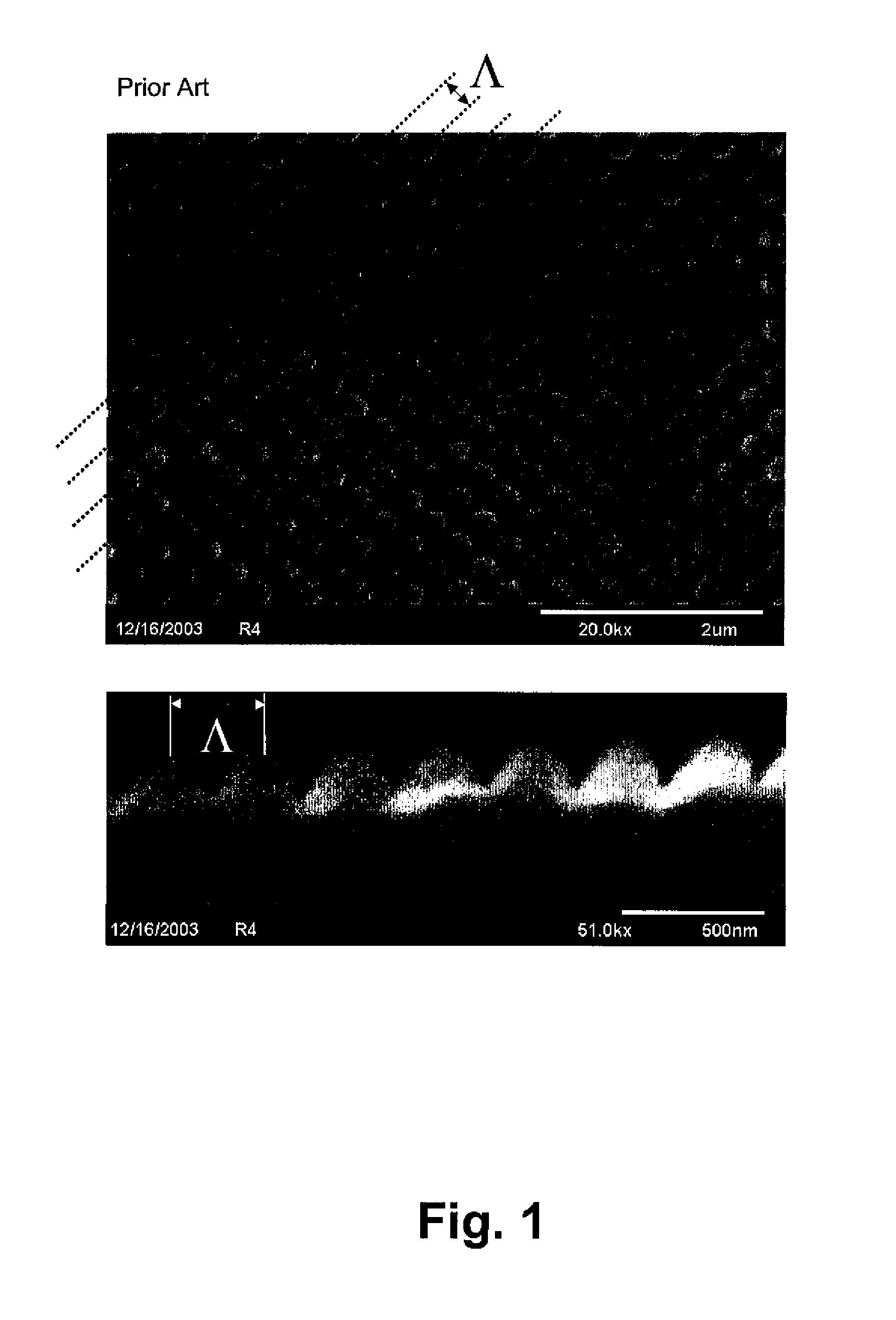
[0063]FIG. 1 shows scanning electron microscope (SEM) photographs of a Motheye anti-reflection texture molded in a plastic window by a direct casting process. An overhead view and a cross sectional profile are shown. Dashed lines indicate the pattern repeat period, or pitch, labeled as Λ. Cone structures are shown with a spacing of about 250 nanometer (nm), and a comparable depth. The texture is designed to suppress reflected light in the vis...


PUM

PropertyMeasurementUnit
Fractionaaaaaaaaaa
Fractionaaaaaaaaaa
Angleaaaaaaaaaa

Abstract

A surface relief structure consisting of a random distribution of surface features with varying feature profile and depth, is described. The texture serves to suppress the reflection of electromagnetic waves in the optical region of the spectrum without dispersing any portion of the spectrum by diffraction. Processes for fabricating the random distribution anti-reflecting textures in common materials are also described. The disclosed textures are particularly useful as anti-reflecting covers for displays, and as directly molded anti-reflecting surfaces in eyeglass lenses. Other applications such as covers for artwork, and improved solar cells are made practical by the invention.

Description

CROSS REFERENCE TO RELATED APPLICATION[0001]This application claims priority of Provisional Application Ser. No. 60 / 678,126, filed on May 5, 2005 entitled “RANDOM TEXTURE ANTI-REFLECTION OPTICAL SURFACE TREATMENT”.FIELD OF THE INVENTION[0002]This invention relates to methods for the suppression of reflected light from optical devices such as solar panels, electronic imaging sensors, windows and lenses. Anti-reflection treatments are used widely throughout the optics industry in applications ranging from eyeglasses, lasers, cameras, solar cells, and lithography systems operating on the visible and near infrared light spectrum, to windows, missile domes, security cameras, and laser systems operating on the infrared spectrum.BACKGROUND OF THE INVENTION[0003]Information and video displays are used widely in automotive applications, computers, and hand-held devices such as mobile phones and personal digital assistants (PDAs). Light reflecting from instrument panel and center console auto...

Claims


Application Information

Patent Timeline
IPC IPC(8): B29D11/00C03C15/00
CPCB29D11/00432C03C23/006C03C2204/08G02B1/118
Inventor HOBBS, DOUGLAS S.
Owner COHO HLDG
Why Eureka
Try Eureka