Coated sleeved oil and gas well production devices

a technology for oil and gas wells and sleeves, applied in the direction of drilling casings, drilling pipes, borehole/well accessories, etc., can solve the problems of device wear, deformation, device wear, etc., and achieve the effect of reducing friction, wear, corrosion, erosion and deposits

Active Publication Date: 2012-10-16
EXXONMOBIL UPSTREAM RES CO
View PDF72 Cites 22 Cited by
  • Summary
  • Abstract
  • Description
  • Claims
  • Application Information

AI Technical Summary

Problems solved by technology

Oil and gas well production suffers from basic mechanical problems that may be costly, or even prohibitive, to correct, repair, or mitigate.
Friction is ubiquitous in the oilfield, devices that are in moving contact wear and lose their original dimensions, and devices are degraded by erosion, corrosion, and deposits.
The amount of power which can be transmitted by rotation is limited to the maximum torque a drill string or coiled tubing can sustain.
Friction between the moving surface of the drill stem assembly and the stationary surfaces of the casing and formation creates considerable drag on the drill stem and results in excessive torque and drag during drilling operations.
The problem caused by friction is inherent in any drilling operation, but it is especially troublesome in directionally drilled wells or extended reach drilling (ERD) wells.
As the drill string increases in length or degree of vertical deflection, the amount of friction created by the rotating drill stem assembly also increases.
Areas of increased local curvature may increase the amount of friction generated by the rotating drill stem assembly.
Consequently, the depth to which wells can be drilled using available directional drilling equipment and techniques is ultimately limited by friction.
In industry operations, attempts have been made to reduce friction through, mainly, using water and / or oil based mud solutions containing various types of expensive and often environmentally unfriendly additives.
Diesel and other mineral oils are also often used as lubricants, but there may be problems with the disposal of the mud, and these fluids also lose lubricity at elevated temperatures.
Materials such as Teflon have been used to reduce sliding contact friction, however these lack durability and strength.
Other additives include vegetable oils, asphalt, graphite, detergents, glass beads, and walnut hulls, but each has its own limitations.
However, aluminum is expensive and may be difficult to use in drilling operations, it is less abrasion-resistant than steel, and it is not compatible with many fluid types (e.g. fluids with high pH).
Additionally, the industry has developed means to “float” an inner casing string within an outer string to run casing and liner at high inclinations, but circulation is restricted during this operation and it is not amenable to the hole-making process.
As a result, the torque needed for the rotary drilling operation, especially directional drilling, is decreased.
A tungsten carbide containing alloy, such as Stellite 6 and Stellite 12 (trademark of Cabot Corporation), has excellent wear resistance as a hardfacing material but may cause excessive abrading of the opposing device.
Arnco markets this device under the trade name “WearSleeve.” After several years of availability in the market and at least one field test, this system has not been used widely.
There are many additional pieces of equipment that have metal-to-metal contact on a drilling rig that are subject to friction, wear, erosion, corrosion, and / or deposits.
Most of these operations comprise the axial or torsional motion of one body relative to another, wherein the two bodies are in mechanical contact with a certain contact force and contact friction that resists the relative motion, causing friction and wear.
In a marine environment, a further complication is that the wellhead tree may be “dry” (located above sea level on the platform) or “wet” (located on the seafloor).
Risers may be particularly susceptible to the issues associated with rotating an inner pipe within an outer stationary pipe since the risers are not fixed but may also move due to contact with not only the drill string but also the sea environment.
Common to most OCTG (but not coiled tubing) are threaded connections, which are subject to potential failure resulting from improper thread and / or seal interference, leading to galling in the mating connectors that can inhibit use or reuse of the entire joint of pipe due to a damaged connection.
However, there are still problems today with thread galling and interference issues, particularly with the more costly OCTG material alloys for extreme service requirements.
Chokes and flowlines connected to the wellhead (particularly joints and elbows) are subject to friction, wear, corrosion, erosion, and deposits.
Chokes may be cut out by sand flowback, for example, rendering the measurement of flow rates inaccurate.
Many devices (sleeves, pockets, nipples, needles, gates, balls, plugs, crossovers, couplings, packers, stuffing boxes, valve stems, centrifuges, etc.) are subject to friction and mechanical degradation due to corrosion and erosion, and even potential blockage resulting from deposits of scale, asphaltenes, paraffins, and hydrates.
Some of these devices may be installed downhole or on the sea floor, and it may be impossible or very costly at best to gain service access for repair or restoration.
The placement of these tools, particularly in extended-reach wells, may be impeded by friction drag.
This operation may involve deploying a special-purpose large diameter assembly comprising one of several types of sand screen mesh designs over a central “base pipe.” The screen and basepipe are frequently subject to erosion and corrosion and may fail due to sand “cutout.” Also, in high inclination wells, the frictional drag resistance encountered while running screens into the wellbore may be excessive and limit the application of these devices, or the length of the wellbore may be limited by the maximum depth to which screen running operations may be conducted due to friction resistance.
Furthermore, the proppant particles are subject to crushing and generating “fines” that increase the resistance to fluid flow during production.
However, many wells at some point in their life require assistance in lifting fluids out of the wellbore.
Interfaces between parts (sleeves, pockets, plugs, packers, crossovers, couplings, bores, mandrels, etc.) are subject to friction and mechanical degradation due to corrosion and erosion, and even potential blockage or mechanical fit interference resulting from deposits of scale, asphaltenes, paraffins, and hydrates.
First, the methods to apply the inventive coatings on production devices may require that the body be enclosed in a chamber.
This may be a very restrictive requirement for many oilfield components.
For example, the geometry of long pipe sections is cumbersome for such chambers.
This is also not likely to be very efficient since the surface area to be coated may be a small fraction of the total surface area of the main body.
The sleeve element may be subjected to high temperatures and other environmental conditions during the coating process that would cause damage to the other elements of the system.
The prior art does not disclose an efficient means to address these problems, and the inventive methods will enable the use of low-friction coatings in oil and gas well production devices.

Method used


Image

  • Coated sleeved oil and gas well production devices
  • Coated sleeved oil and gas well production devices
  • Coated sleeved oil and gas well production devices

Examples


example 1

Illustrative Example 1

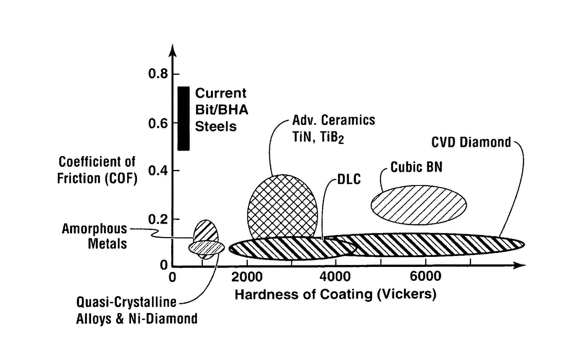
[0267]DLC coatings were applied on 4142 steel substrates by vapor deposition technique. DLC coatings had a thickness ranging from 1.5 to 25 micrometers. The hardness was measured to be in the range of 1,300 to 7,500 Vickers Hardness Number. Laboratory tests based on ball on disk geometry have been conducted to demonstrate the friction and wear performance of the coating. Quartz ball and mild steel ball were used as counterface materials to simulate open hole and cased hole conditions respectively. In one ambient temperature test, uncoated 4142 steel, DLC coating and commercial state-of-the-art hardbanding weld overlay coating were tested in “dry” or ambient air condition against quartz counterface material at 300 g normal load and 0.6 m / sec sliding speed to simulate an open borehole condition. Up to 10 times improvement in friction performance (reduction of friction coefficient) over uncoated 4142 steel and hardbanding could be achieved in DLC coatings as shown...

example 2

Illustrative Example 2

[0272]In the laboratory wear / friction testing, the velocity dependence (velocity weakening or strengthening) of the friction coefficient for a DLC coating and uncoated 4142 steel was measured by monitoring the shear stress required to slide at a range of sliding velocity of 0.3 m / sec˜1.8 m / sec. Quartz ball was used as a counterface material in the dry sliding wear test. The velocity-weakening performance of the DLC coating relative to uncoated steel is depicted in FIG. 23. Uncoated 4142 steel exhibits a decrease of friction coefficient with sliding velocity (i.e. significant velocity weakening), whereas DLC coatings show no velocity weakening and indeed, there seems to be a slight velocity strengthening of COF (i.e. slightly increasing COF with sliding velocity), which may be advantageous for mitigating torsional instability, a precursor to stick-slip vibrations.

example 3

Illustrative Example 3

[0273]Multi-layered DLC coatings were produced in order to maximize the thickness of the DLC coatings for enhancing their durability for drill stem assemblies used in drilling operations. In one form, the total thickness of the multi-layered DLC coating varied from 6 μM to 25 μm. FIG. 24 depicts SEM images of both single layer and multilayer DLC coatings for drill stem assemblies produced via PECVD. An adhesive layer(s) used with the DLC coatings was a siliceous buffer layer.


PUM


Abstract

Provided are coated sleeved oil and gas well production devices and methods of making and using such coated sleeved devices. In one form, the coated sleeved oil and gas well production device includes an oil and gas well production device including one or more bodies and one or more sleeves proximal to the outer or inner surface of the one or more bodies, and a coating on at least a portion of the inner sleeve surface, outer sleeve surface, or a combination thereof, wherein the coating is chosen from an amorphous alloy, a heat-treated electroless or electro plated based nickel-phosphorous composite with a phosphorous content greater than 12 wt %, graphite, MoS2, WS2, a fullerene based composite, a boride based cermet, a quasicrystalline material, a diamond based material, diamond-like-carbon (DLC), boron nitride, and combinations thereof. The coated sleeved oil and gas well production devices may provide for reduced friction, wear, erosion, corrosion, and deposits for well construction, completion and production of oil and gas.

Description

CROSS-REFERENCE TO RELATED APPLICATIONS[0001]This application is a Continuation-in-Part of U.S. patent application Ser. No. 12 / 583,302, filed Aug. 18, 2009, and U.S. patent application Ser. No. 12 / 583,292, filed Aug. 18, 2009, and claims priority of U.S. Provisional Application Ser. No. 61 / 207,814, filed Feb. 17, 2009, and U.S. Provisional Application Ser. No. 61 / 189,530, filed Aug. 20, 2008, the contents of each are hereby incorporated by reference.FIELD[0002]The present disclosure relates to the field of oil and gas well production operations. It more particularly relates to the use of coated sleeved devices to reduce friction, wear, corrosion, erosion, and deposits in oil and gas well production operations. Such coated sleeved oil and gas well production devices may be used in drilling rig equipment, marine riser systems, tubular goods (casing, tubing, and drill strings), wellhead, trees, and valves, completion strings and equipment, formation and sandface completions, artificial...

Claims


Application Information

Patent Timeline
Patent Type & Authority Patents(United States)
IPC IPC(8): E21B17/10
CPCE21B17/042E21B17/1085E21B41/00
Inventor BAILEY, JEFFREY ROBERTSBIEDIGER, ERIKA ANN OOTENBANGARU, NARASIMHA-RAO VENKATABANGARU, LEGAL REPRESENTATIVE, SWARUPA SOMAOZEKCIN, ADNANJIN, HYUN-WOOERTAS, MEHMET DENIZAYER, RAGHAVANELKS, WILLIAM CURTISYEH, CHARLES SHIAO-HSIUNGBARRY, MICHAEL DAVIDHECKER, MICHAEL THOMAS
Owner EXXONMOBIL UPSTREAM RES CO
Why Eureka
Try Eureka