Heat dissipation device based on carbon nanotube arrays and low temperature co-fired ceramics and preparation method

A technology of low-temperature co-fired ceramics and carbon nanotube arrays, which is applied in cooling/ventilation/heating transformation, semiconductor/solid-state device manufacturing, semiconductor/solid-state device components, etc., and can solve low efficiency, increased cost, and poor heat transfer performance and other issues, to achieve simple process conditions, facilitate batch processing, and achieve simple effects

Inactive Publication Date: 2010-09-08
PEKING UNIV
View PDF4 Cites 25 Cited by
  • Summary
  • Abstract
  • Description
  • Claims
  • Application Information

AI Technical Summary

Problems solved by technology

[0004] (1) Natural convection heat dissipation uses the gaps of various components in the equipment and the heat conduction, convection and radiation of the casing to achieve the purpose of heat dissipation. The advantages are simple structure, low cost, safety and reliability, no noise and vibration, but the thermal resistance is large. Poor thermal performance, suitable for low temperature control requirements, heat flux less than 0.08W/cm 2 Low-power electronics and components for
[0005] (2) Forced air cooling and heat dissipation rely on fans (centrifugal, axial flow, propeller) to force the air around the device to take away the heat emitted by the device. The heat transfer is 10 times larger than natural convection and radiation, but the cost increase, the noise becomes larger, and the operation reliability is lower
It has no noise and vibration, small size, compact structure,...

Method used


Image

  • Heat dissipation device based on carbon nanotube arrays and low temperature co-fired ceramics and preparation method
  • Heat dissipation device based on carbon nanotube arrays and low temperature co-fired ceramics and preparation method
  • Heat dissipation device based on carbon nanotube arrays and low temperature co-fired ceramics and preparation method

Examples


Embodiment Construction

[0029] The present invention will be further described below in conjunction with the examples, but the present invention is not limited to the following examples.

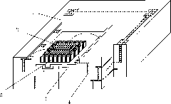
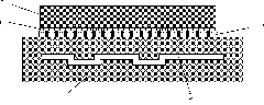
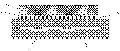
[0030] Low temperature co-fired ceramic substrate (Low Temperature Co-fired Ceramic, referred to as LTCC) has a low sintering temperature (less than 950°C), and good metal conductors such as Au, Ag, and Cu with high conductivity can be used as interconnect wiring and via hole fillers. Improve the quality factor of the circuit system and reduce signal loss; screen printing, photolithography and other processes can realize micro-wiring, and produce fine-structured circuits with a line width of less than 50 μm; the dielectric constant of the substrate is only 4-5, which is lower than most commonly used substrates Material, signal transmission delay is small, high-frequency, high-Q performance is excellent, the operating frequency can be as high as tens of GHz, suitable for high-frequency / high-speed signal transmission;...


PUM


Abstract

The invention provides a heat dissipation device based on carbon nanotube arrays and low temperature co-fired ceramics and a preparation method, belonging to the heat dissipation technology of microelectronic devices. The heat dissipation device comprises a low temperature co-fired ceramic substrate with a micro channel embedded inside. Carbon nanotube arrays are prepared on the surface of the low temperature co-fired ceramic substrate and a heating device connected with a circuit of the low temperature co-fired ceramic substrate is fixed on the carbon nanotube arrays. The device makes the most of the advantage that the low temperature co-fired ceramic substrate is easy to be machined into three-dimensional structure, the micro channel is manufactured in the substrate and most heat generated by the heating device is led away through convective heat exchange of the micro channel; and meanwhile, the carbon nanotube arrays and the low temperature co-fired ceramics are closely jointed with the heating device, thus reducing the microvoids generated on the joint interface by the traditional methods such as welding, avoiding heat resistance caused by the microvoids, weakening the heat resistance between the heating device and the low temperature co-fired ceramic substrate and improving the heat dissipation capability of the heat dissipation device.

Description

technical field [0001] The invention belongs to the heat dissipation technology of microelectronic devices, in particular to a heat dissipation device and a preparation method based on carbon nanotube arrays and low-temperature co-fired ceramics. Background technique [0002] With the development of information technology in society, miniaturization and multi-functional products have gradually become the trend and trend of electronic technology development. On the one hand, the smaller the size of the device, the better, and it has developed from micron to nanometer. On the other hand, the size of the device Since 1959, the degree of integration has been increasing at a high rate of 40-50% per year, and there are hundreds of thousands of components on each chip. The heat flux generated by the current computer CPU chip during work has reached 60-100W / cm 2 , according to the large-scale integrated circuit development map compiled by the US Semiconductor Industry Association S...

Claims


Application Information

Patent Timeline
IPC IPC(8): H01L23/473H01L23/367H01L23/373H01L21/50H01L21/48H05K7/20
CPCH01L2924/0002H01L2224/48091H01L2224/48227
Inventor 白树林张杨飞
Owner PEKING UNIV
Why Eureka
Try Eureka