
Grapheme foam and preparation method thereof

A graphene foam and graphene technology, applied in gaseous chemical plating, metal material coating process, coating, etc., can solve problems such as difficult to disperse, easy to agglomerate, efficient energy storage limitations, etc., to prevent agglomeration, specific surface area The effect of enhancement and simple preparation process

Inactive Publication Date: 2010-09-15
INST OF CHEM CHINESE ACAD OF SCI
View PDF2 Cites 93 Cited by
  • Summary
  • Abstract
  • Description
  • Claims
  • Application Information

AI Technical Summary

Problems solved by technology

The two-dimensional structure of graphene makes it easy to agglomerate and difficult to disperse. The high surface area obtained by the liquid phase dispersion method is difficult to maintain in the subsequent processing, which limits its high-efficiency energy storage.

Method used


Image

  • Grapheme foam and preparation method thereof
  • Grapheme foam and preparation method thereof
  • Grapheme foam and preparation method thereof

Examples


Embodiment 1

[0037] Embodiment 1, prepare graphene foam

[0038] The first step is to clean the nickel foam template

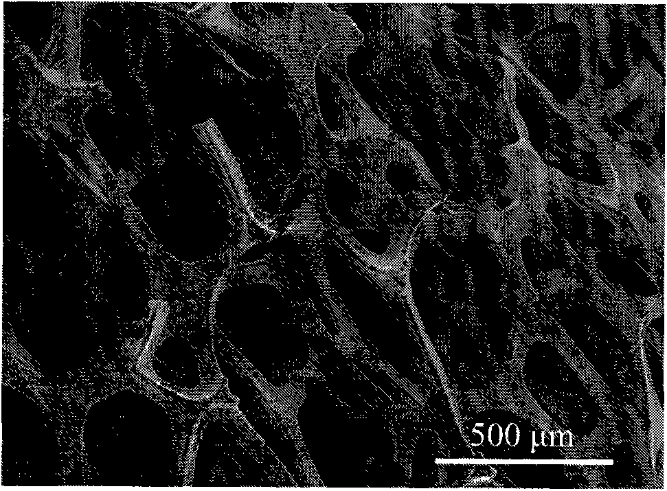
[0039] Nickel foam ( figure 1 ) were sequentially ultrasonically cleaned with deionized water, acetone, and ethanol for 30 minutes and dried;

[0040] The second step is to calcinate the nickel foam template

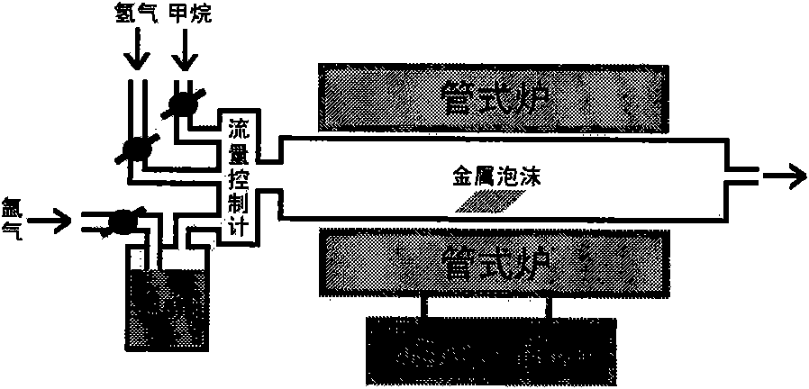
[0041] The experimental equipment used is as figure 2 As shown, put the nickel foam into the quartz tube of the tube furnace, evacuate to reduce the pressure in the tube to below 10Pa, and then inject hydrogen to the normal pressure, and repeatedly remove the air in the tube three times. Control the hydrogen flow rate to 50 sccm, heat up the temperature, and when the temperature rises to 1000°C, continue to keep the temperature constant for 0.5-1 hour;

[0042] The third step, growing graphene (that is, preparing graphene-modified nickel foam)

[0043] Maintain the temperature at 1000°C, feed methane and hydrogen, the gas flow rate is 30sccm methane, 50sccm hydro...

Embodiment 2

[0048] Embodiment 2, prepare graphene foam

[0049] According to the preparation method in Example 1, after calcining at 1000° C. for 0.5-1 hour, the temperature was lowered to 850° C., and 30 sccm argon was passed into a tank containing ethanol for bubbling, and ethanol was a carbon source for graphene growth. Scanning electron microscopy characterization of the as-prepared graphene-modified nickel foam, as Figure 8 shown. Graphene is attached to the surface of nickel foam, and there are wrinkles in graphene due to the different shrinkage coefficients of graphene and nickel foam.

Embodiment 3

[0050] Embodiment 3, prepare graphene foam

[0051] According to the preparation method in Example 1, the difference is that the copper foam is used as a growth template, and the copper foam is removed with a concentration of 0.05-0.1g / ml ferric chloride or ferric nitrate, the scanning electron of the prepared graphene-modified copper foam Microscopic characterization, such as Figure 9 shown. Graphene is attached to the surface of copper foam, and there are wrinkles in graphene due to the different shrinkage coefficients of graphene and copper foam.


PUM

PropertyMeasurementUnit
Apertureaaaaaaaaaa

Abstract

The invention discloses grapheme foam and a preparation method thereof. The grapheme foam provided by the invention is prepared by the method comprising the following steps: 1) putting a metal foam material into a vacuum tube type furnace, and calcining the metal foam material under non-oxidizing atmosphere; 2) depositing grapheme on the calcined metal foam material by adopting a chemical vapor deposition method; and 3) removing foam metal from the obtained grapheme modified metal foam material, cleaning the obtained foam material by using deionized water, ethanol and ether in turn, taking the foam material out and drying the foam material to obtain grapheme foam. The grapheme foam material has a three-dimensional hollow porous netlike structure, the grapheme is on the netlike wall, and the structural characteristic effectively prevents the agglomeration of the grapheme; and the grapheme foam material integrates the characteristics of a foam material and a conductive material, and has the advantages of ultra-low density, ultra-high surface area, high heat conduction, high temperature resistance, corrosion resistance and the like.

Description

technical field [0001] The invention relates to a novel material graphene foam and a preparation method thereof. Background technique [0002] Carbon materials play a vital role in today's science and technology. Carbon is ubiquitous in nature and can form the crystal structures of diamond and graphite. With the discovery of fullerenes and carbon nanotubes, people have a new understanding of carbon materials. Two-dimensional graphene is another recently discovered form of carbon. This material has excellent mechanical, physical, chemical and optical properties. At present, people have prepared high-performance graphene samples by using mechanical exfoliation, silicon carbide epitaxial growth, graphite oxide reduction, ultrasonic dispersion and chemical vapor deposition (K.S.Novoselov, A.K.Geim, Science 2004, 306, 666.; C.Berger, Z .Song, X.Li, Science 2006, 312, 1191.; V.C.Tung, M.J.Allen, Nat.Nanotechnol.2009, 4, 25.; Y.Hemandez, V.Nicolosi, Nat.Nanotechnol.2008, 3, 563...

Claims


Application Information

Patent Timeline
IPC IPC(8): C23C16/26
Inventor 刘云圻陈建毅黄丽平薛运周武斌于贵
Owner INST OF CHEM CHINESE ACAD OF SCI
Learn More