
Method for manufacturing three-dimensional micromixer microfluidic chip

A technology of microfluidic chips and manufacturing methods, applied in chemical instruments and methods, laboratory containers, laboratory utensils, etc., can solve problems such as complex processes, and achieve simple operation, good reproducibility, and low cost Effect

Inactive Publication Date: 2011-11-16
INST OF CHEM CHINESE ACAD OF SCI
View PDF1 Cites 26 Cited by
  • Summary
  • Abstract
  • Description
  • Claims
  • Application Information

AI Technical Summary

Problems solved by technology

But they often involve many layers of assembly, and the process is more complicated

Method used


Image

  • Method for manufacturing three-dimensional micromixer microfluidic chip
  • Method for manufacturing three-dimensional micromixer microfluidic chip
  • Method for manufacturing three-dimensional micromixer microfluidic chip

Examples


Embodiment 1、3

[0031] Example 1, Fabrication of 3D micro-mixed microfluidic chip

[0032] (1) Design the microchannel pattern of the 3D micro-hybrid microfluidic chip with Freehand software, the width is designed to be 100 μm, and the mask is prepared by laser phototypesetting;

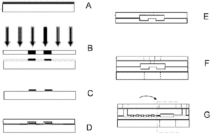
[0033] (2) Piranha washing solution (98% (wt) H 2 SO 4 with 30% (wt) H 2 o 2 The volume ratio is 3:1) heated, boiled and cleaned for 30min, rinsed with distilled water, dried and placed in a KW-4A glue homogenizer, and coated with a layer of SU-8 photolithography with a thickness of about 50μm at a speed of 4000r / min. glue (model SU-82035), such as figure 1As shown in step A; after that, let the glass sheet coated with light glue stand for 30 minutes to make it flow naturally and adjust the plane evenly; place the glass sheet coated with glue in a constant temperature hot plate oven for 20 minutes at 65°C, and immediately heat up the oven to 95°C, after the temperature of the oven is constant, bake it for 10 mi...

Embodiment 2

[0037] The 3D micro-mixed microfluidic chip made in Example 2 and Example 1 is used in combination with an ultraviolet detector

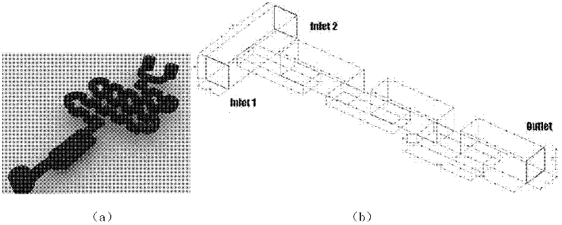
[0038] Assembly of 3D micro-hybrid microfluidic chip-ultraviolet detector: 3D micro-hybrid microfluidic chip needs to work under the positive pressure drive of the micro-injection pump; The silicone tube is used as the catheter to transport the sample, and the polyurethane plastic tube with an inner and outer diameter of 2×3 mm is used as the sample connection port, and the polyurethane tube and the glass chip sample port are bonded with epoxy AB glue (1:1, v / v). and 1000 μm micro-sampler sample injection, directly connected to the sampler needle with a silicone tube, with TS-1A micro-syringe pump to control the input flow (flow rate) to directly drive the sample injection; in addition, the 3D micro-mix micro The fluidic chip is loaded into a self-designed plexiglass mold, so that the detection area of ​​the 3D micro-hybrid microfluidic chip is alig...


PUM


Abstract

The invention discloses a method for manufacturing a three-dimensional micromixer microfluidic chip, which comprises the following steps: (1) making a mask by the microchannel graph of the three-dimensional micromixer microfluidic chip by laser photocomposition; (2) coating negative photoresist on a glass slide, laying the mask on the negative photoresist, exposing the glass slide covered with the negative photoresist and mask in an ultraviolet light source and developing to obtain a negative photoresist film; (3) casting mixed pulp of polydimethylsiloxane main agent and a curing agent on the negative photoresist film, curing, removing the negative photoresist film and thus obtaining a polydimethylsiloxane chip A; (4) making a polydimethylsiloxane chip B by the steps (1), (2) and (3); and (5) tightly laminating and bonding the polydimethylsiloxane chip A and the polydimethylsiloxane chip B to obtain the three-dimensional micromixer microfluidic chip. The method is simple in operation, low in cost, short in manufacturing period and high in repeatability and is very suitable for processing microstructures which are scores of micrometers long.

Description

technical field [0001] The invention relates to a manufacturing method of a 3D micro-mixing microfluidic chip. Background technique [0002] An important operation of microfluidic chips in the fields of biochemical analysis, drug delivery, and nucleic acid sequencing is rapid mixing. Different from the macroscopic system, the mixing of fluids at the microscopic scale is mainly diffusion and mass transfer under laminar flow, and the diffusion of molecules is very slow, so it is difficult to achieve mixing in microfluidic channels. By inputting energy, micro-mixing can be achieved in microchannels with the help of external forces such as magnetic force, electric field force, acoustic field force, air pressure, and centrifugal force, but the systems and processes involved are relatively complicated (Nam-rung, N. and W. Zhigang. J. Micromech. Microeng. 2005, 15(2), R1). Scientists have found that if a certain form of geometric modification is made to the internal or external s...

Claims


Application Information

Patent Timeline
Patent Type & Authority Applications(China)
IPC IPC(8): B01J19/00B01L3/00G01N21/25
Inventor 江龙韩建华张建平李兴长
Owner INST OF CHEM CHINESE ACAD OF SCI
Learn More