
Wear-resistant graphene surface modification method

A graphene surface and graphene technology, applied in the field of lubricating materials and wear-resistant graphene surface modification, to achieve the effects of increased wear life, reduced production costs, and low friction coefficient

Inactive Publication Date: 2013-07-31
魏颖
View PDF4 Cites 15 Cited by
  • Summary
  • Abstract
  • Description
  • Claims
  • Application Information

AI Technical Summary

Problems solved by technology

[0007]However, at present, there are few studies on the use of graphene's excellent lubricating properties in micro-nano electromechanical systems. Some scholars use chemical adsorption and thermal reduction of graphene oxide to Redox graphene (RGO) was prepared on a silicon wafer by a one-step reaction method, and its friction and wear properties were analyzed. However, the graphene prepared by this method has many defects and the process is complicated; Graphene is grown and then transferred to a silicon wafer. The graphene measured by this method has good anti-adhesion and lubrication properties, but the load it bears is small (5-70mN), and the friction life is low

Method used


Image

  • Wear-resistant graphene surface modification method
  • Wear-resistant graphene surface modification method
  • Wear-resistant graphene surface modification method

Examples


Embodiment 1

[0044] 1) The preparation of graphene by chemical vapor deposition is divided into the following steps:

[0045] The first step, copper foil surface pretreatment: first put 25μm copper foil into a tube furnace, heat it from room temperature to 1000°C at a heating rate of 10-20°C / min, and keep it for 30 minutes. hydrogen;

[0046] The second step is the process of graphene growth: stop hydrogen, continue to feed methane at 20 sccm, and treat at 1000°C for 10 minutes; stop methane, continue to feed hydrogen at 15 sccm, and cool down to room temperature at a rate of 100°C / min. long graphene;

[0047] The third step is the transfer process of graphene on copper foil: Spin-coat polymethyl methacrylate (PMMA) with a mass concentration of 3% on the surface of copper foil with graphene, dry it at 120°C for 10 minutes, and then Copper foil coated with PMMA was transferred to 5mol / L FeCl 3 Soak in the solution for 2 hours to remove excess copper foil to obtain PMMA / graphene, after 3-...

Embodiment 2

[0056] 1) The preparation of graphene by chemical vapor deposition is divided into the following steps:

[0057] The first step, copper foil surface pretreatment: first put 25μm copper foil into a tube furnace, heat it from room temperature to 1000°C at a heating rate of 10-20°C / min, and keep it for 30 minutes. hydrogen;

[0058] The second step is the process of graphene growth: stop hydrogen, continue to feed methane at 20 sccm, and treat at 1000°C for 10 minutes; stop methane, continue to feed hydrogen at 15 sccm, and cool down to room temperature at a rate of 100°C / min. long graphene;

[0059] The third step is the transfer process of graphene on copper foil: Spin-coat polymethyl methacrylate (PMMA) with a mass concentration of 3% on the surface of copper foil with graphene, dry it at 120°C for 10 minutes, and then Copper foil coated with PMMA was transferred to 5mol / L FeCl 3 Soak in the solution for 2 hours to remove excess copper foil to obtain PMMA / graphene, after 3-...

Embodiment 3

[0069] Friction test conditions:

[0070] The friction test is done on the UMT-2MT friction testing machine, using the ball-on-disk contact mode, the friction load and frequency are 0.1N and 1Hz respectively. The steel ball with a diameter of 3-5mm and a roughness of 0.02-0.06 μm is the contact pair, and the friction adopts Sliding way, the sliding distance is 0.5 cm. The entire rubbing process was done in a room with an ambient temperature of 25°C and a relative humidity of 26%.

[0071] It can be seen from Figure 4a that the friction coefficient of the graphene with the columnar array structure without metal embedded on the substrate surface is about 0.2, and the friction coefficient increases rapidly after 800 seconds of friction, and the graphene is destroyed.

[0072] Figure 4b shows that the friction coefficient of the graphene embedded in the surface of the metal columnar array structure of the present invention is similar to the former, but the whole friction process ...


PUM

PropertyMeasurementUnit
thicknessaaaaaaaaaa
breaking strengthaaaaaaaaaa
diameteraaaaaaaaaa

Abstract

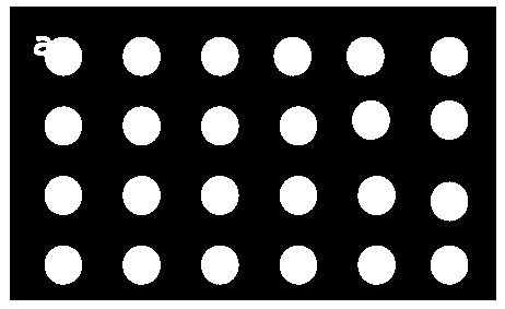
The invention relates to a wear-resistant graphene surface modification method, which adopts a magnetron sputtering technology to embed metal elements into the surface of graphene to form a column-shaped array structure and fulfills the aims of reducing friction and prolonging wear-resistant life through surface micro-structuration. The wear-resistant graphene surface modification method comprises the following steps of: 1) preparing the graphene by a chemical vapor deposition method; and 2) embedding the column-shaped array structure into the surface of the graphene, wherein the step 2) comprises the following steps of: 1, placing the graphene and a substrate into a magnetron sputtering furnace and placing a metal mask plate on the surface of the graphene, wherein the metal mask plate is provided with holes arranged in an array mode and a source electrode is a 99.99 percent pure metal target; 2, turning on a vacuum pump, vacuumizing in the magnetron sputtering furnace to the ultimate vacuum of 1.0*10<-5>Pa-5.0*10<-5>Pa, introducing high-purity argon until the gas pressure is 2 to 6 Pa and pre-bombarding a test sample for about 1 to 3 minutes; 3, sputtering under the power of 30 to 80 W at room temperature for 10 to 15 minutes; and 4, turning off a power supply of the source electrode, vacuumizing the furnace to ultimate vacuum, cooling to room temperature and discharging from the furnace.

Description

Technical field: [0001] The invention relates to a film preparation, in particular to a wear-resistant graphene surface modification method, which belongs to lubricating materials. Background technique: [0002] Micro-Electro-Mechanical Systems (MEMS) are usually intelligent systems that integrate mechanical, electronic, optical and other functional components on a single or multi-chip chip material to manufacture mechatronic systems with a size below a millimeter. Because MEMS has the characteristics of small scale, light weight, low energy consumption, high reliability, and strong functions, the currently developed micro-manipulators, micro-valves, micro-pumps, micro-turbines and micro-robots with various functions have been used in biology, It is widely used in the fields of medicine, environment, aerospace, agriculture, industry and military. However, with the significant reduction of the characteristic scale, the ratio of the surface area to the volume of the MEMS i...

Claims


Application Information

Patent Timeline
Patent Type & Authority Applications(China)
IPC IPC(8): C23C28/00C23C16/26C23C16/56C23C14/18
Inventor 吴红艳顾正彬徐林华王俊峰郭亦佳
Owner 魏颖
Learn More