Titanium oxide coating/foam silicon carbide structure catalytic carrier and preparation method thereof

A technology of silicon carbide foam and catalytic carrier, which is applied in the direction of catalyst carrier, chemical instrument and method, physical/chemical process catalyst, etc., can solve the problems of unfavorable titanium oxide catalytic performance, catalyst wear, complicated operation, etc., and achieve unique catalytic performance, Efficiency improvement, absorption efficiency improvement effect

Active Publication Date: 2013-10-23
INST OF METAL RESEARCH - CHINESE ACAD OF SCI
View PDF4 Cites 13 Cited by
  • Summary
  • Abstract
  • Description
  • Claims
  • Application Information

AI Technical Summary

Problems solved by technology

The problem of powder is that the separation cost of the catalyst and the reaction medium is high and the operation is complicated; while the particle catalyst has the contradictions of poor heat transfer capacity of the catalyst bed, difficulty in balancing the bed pressure drop and the diffusion layer, and serious catalyst wear; (2) with The coating method is loaded on the surface of porous ceramics. After porous ceramics are loaded with titanium oxide, the specific surface of the overall catalyst is higher, which is conducive to the full utilization of titanium oxide. However, the pore connectivity rate of ordinary porous ceramics is low, and the circulation of liquid or gas in it The resistance is large, which is not conducive to the further improvement of the catalytic performance of titanium oxide
In addition, ordinary porous ceramics only act as a carrier and have no effect on the catalytic purification ability of titanium oxide.

Method used


Image

  • Titanium oxide coating/foam silicon carbide structure catalytic carrier and preparation method thereof
  • Titanium oxide coating/foam silicon carbide structure catalytic carrier and preparation method thereof
  • Titanium oxide coating/foam silicon carbide structure catalytic carrier and preparation method thereof

Examples


Embodiment 1

[0032] In this embodiment, the preparation process of the silicon carbide foam ceramic structure catalyst carrier with nano-titanium oxide coating is as follows:

[0033] 1. Prepare a slurry with a weight ratio of silicon carbide micropowder (average particle size 10nm): epoxy resin: iron micropowder: dehydrated alcohol=100:50:0.75:50, and ball mill it for 2 hours before use.

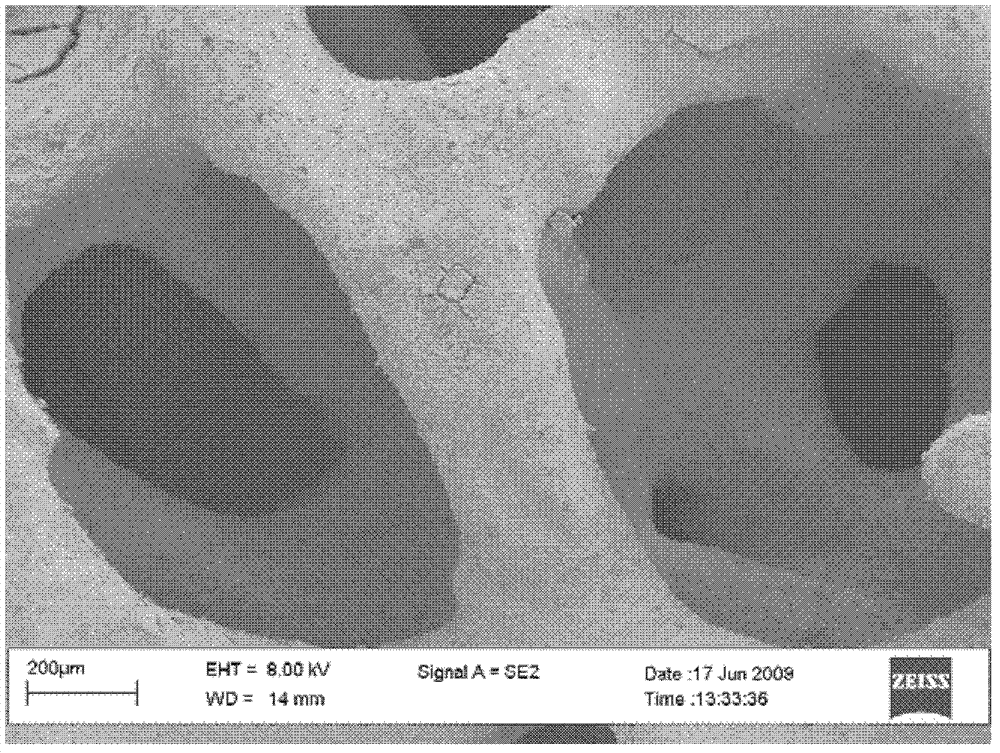
[0034] 2. Immerse the polyurethane foam in the above slurry for 2 minutes, blow off the excess slurry with compressed air after taking it out, dry it at 150°C and weigh it. Repeat the above process until the required weight (0.95 g / ml) is reached to obtain a foamed silicon carbide precursor.

[0035] 3. The foamed silicon carbide precursor obtained in step 2 was pyrolyzed at 800°C for 0.5 hours under the protection of argon. After pyrolysis, the sample was sintered at 1600°C for 1 hour under a silicon atmosphere to obtain foamed silicon carbide with P-type semiconductor characteristics. Foamed silicon ...

Embodiment 2

[0042]1. Slurry is prepared in the ratio of silicon carbide micropowder (average particle size 10 μm) by weight: phenolic resin: iron element in iron oxide micropowder: dehydrated alcohol=100:120:2:80, and it is standby after ball milling for 2 hours.

[0043] 2. Immerse the polyurethane foam in the above slurry for 5 minutes, blow off the excess slurry with compressed air after taking it out, dry it at 50°C, dip it again and dry it, and repeat it several times until the dried sample meets the requirements. The weight (1 g / mL) to obtain a foamed silicon carbide precursor.

[0044] 3. The foamed silicon carbide precursor obtained in step 2 was pyrolyzed at 1200°C for 0.5 hours under the protection of nitrogen. After pyrolysis, the sample was sintered at 1700°C for 2 hours under a silicon atmosphere to obtain foamed silicon carbide with P-type semiconductor characteristics. The foam Silicon carbide was treated in 4M sodium hydroxide solution at 100°C for 10 minutes to increase t...

Embodiment 3

[0051] The difference from Example 1 is:

[0052] The slurry was prepared in the ratio of silicon carbide micropowder (average particle size 50nm):furfural resin:nickel micropowder:absolute ethanol=100:50:0.75:50 by weight, and ball milled for 2 hours before use.

[0053] After the polyurethane foam was dipped in the above slurry and dried several times, the dried sample reached the required weight (1.35 g / ml), and a foamed silicon carbide precursor was obtained.

[0054] A suspension was prepared at a weight ratio of titania sol: titania microparticles: nitrogen element in ammonium chloride = 100:15:7.5, and ball milled for 1 hour to obtain coating slurry.

[0055] After soaking the foamed silicon carbide in the coating slurry and drying it for several times, the coating load reached the required weight (0.15 g / ml).

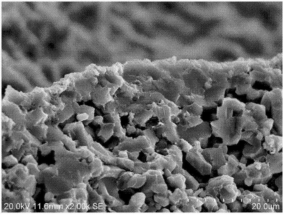
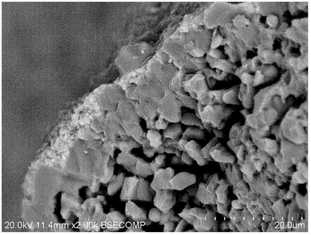
[0056] In this embodiment, the weight content of the titanium oxide coating is 10%, and the rest is a foamed silicon carbide matrix. The fracture micrograph o...


PUM

PropertyMeasurementUnit
thicknessaaaaaaaaaa
particle sizeaaaaaaaaaa
pore sizeaaaaaaaaaa

Abstract

The invention relates to the filed of structure catalyzers, and particularly discloses a titanium oxide coating / foam silicon carbide structure catalytic carrier and a preparation method thereof. A structure catalyzer is utilized to achieve the purposes that a mass and heat transfer effect is enhanced, the dosage of the catalyzer is reduced, the transportation consumption and the power dissipation are reduced, and the like. The structure catalytic carrier is composed of a foam silicon carbide base body and a nanometer titanium oxide coating coated on the surface of the foam silicon carbide basal body, wherein the weight ratio of titanium oxide to the foam silicon carbide base body is (1-50) to (50-300), so that foam silicon carbide can present a P-type semiconductor characteristic through controlling and regulating preparation conditions of a catalyzer, a titanium oxide coating material can present an N-type semiconductor characteristic, furthermore, the whole catalyzer can macroscopically present a P-N node effect, the absorption efficiency of the titanium oxide coating in a visible light range is improved, and the catalyzer can improve the catalytic degradation efficiency of a pollutant in a water solution under visible light illumination.

Description

technical field [0001] The invention relates to the field of structural catalyst carriers, in particular to a catalyst carrier with a titanium oxide coating / foamed silicon carbide structure and a preparation method thereof. Background technique [0002] Titanium dioxide (TiO 2 ) as a wide bandgap semiconductor material has been widely studied and applied in the field of photodegradation and self-cleaning of organic pollutants due to its good chemical stability, safety, non-toxicity, and low cost. In addition to being directly used as a photocatalyst, titanium oxide is also an excellent catalyst carrier, which can cooperate with the catalytically active components loaded on its surface to exhibit unique catalytic properties. [0003] At present, there are two main ways of application of titanium dioxide: (1) Formation and application in the field of catalysis in the form of powder or particles obtained by powder compression and crushing. The problem of powder is that the se...

Claims


Application Information

Patent Timeline
Patent Type & Authority Applications(China)
IPC IPC(8): B01J32/00B01J27/224C02F1/30C02F101/38
Inventor 杨振明张劲松田冲郝栋
Owner INST OF METAL RESEARCH - CHINESE ACAD OF SCI
Why Eureka
Try Eureka