
PERC solar photovoltaic cell capable of improving photoelectric conversion efficiency

A photoelectric conversion efficiency, photovoltaic cell technology, applied in photovoltaic power generation, circuits, electrical components, etc., can solve the problems of reduced battery fill factor, difficult electrode ohmic contact, and reduced carrier life, so as to achieve a smooth diffusion layer surface and improve Battery efficiency, improvement of further improvement effect

Active Publication Date: 2016-02-24
RENESOLA JIANGSU LTD
View PDF4 Cites 11 Cited by
  • Summary
  • Abstract
  • Description
  • Claims
  • Application Information

AI Technical Summary

Problems solved by technology

[0004] PERC battery is the earliest high-efficiency battery researched by the photovoltaic device laboratory of the University of New South Wales in Australia. The front adopts an inverted pyramid structure and is passivated on both sides. The back electrode penetrates the passivation layer and contacts the substrate through some small holes separated far away. The highest efficiency of the prepared battery can reach 23.2%. Since the back electrode is directly in contact with the substrate through some small holes, passivation cannot be achieved here. In order to reduce the carrier recombination here as much as possible, the designed The hole spacing must be much greater than the thickness of the substrate, but the increase in the hole spacing increases the lateral resistance (because the carriers have to travel long distances laterally to get here), which leads to a decrease in the fill factor of the battery; in addition, in It is very difficult to realize the ohmic contact of the electrode on the lightly doped substrate, which limits the high-efficiency PERC cell substrate material to only select specific silicon materials. In order to further improve the performance of the PERC cell, the laboratory envisages adding Localized doping, that is, doping concentrated boron at the contact hole between the electrode and the substrate, this idea has long been proposed, but the biggest difficulty is the realization of the doping process, because the solid-state source used at that time for boron doping Afterwards, the carrier life will be greatly reduced. Later, during the experiment, it was found that the use of liquid source BBr3 for boron doping has little effect on the carrier life of the silicon wafer, and it can be compared with the process of preparing a passivation layer using TCA. Good matching, so it is necessary to develop PERC solar cells with independent intellectual property rights

Method used


Image

  • PERC solar photovoltaic cell capable of improving photoelectric conversion efficiency

Examples


Embodiment 1

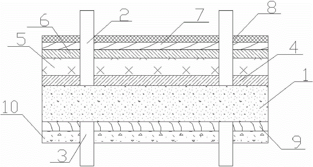
[0042] A PERC solar photovoltaic cell that can improve photoelectric conversion efficiency provided by this embodiment has a structure such as figure 1 As shown, it includes a silicon substrate 1 and a positive electrode 2 and a back electrode 3 directly sintered on the light-facing surface and the back surface of the silicon substrate 1, respectively. The light-facing surface of the silicon substrate 1 is provided with a silicon dioxide layer 4, thickness The first passivation layer 5 of 10-15nm, the anti-reflection layer 6, the conductive film 7 and the transparent glass 8 with a thickness of 100-200nm, and the back side of the silicon substrate 1 is provided with the second passivation layer with a thickness of 7-9nm in sequence. Layer 9 and aluminum back field 10, wherein:

[0043] The first passivation layer 5 and the second passivation layer 9 are aluminum oxide thin films, and the anti-reflection film 6 is a three-layer structure, including the first silicon nitride thi...

Embodiment 2

[0050] This embodiment provides the above-mentioned preparation method of the PERC solar photovoltaic cell that can improve the photoelectric conversion efficiency, which specifically includes the following steps:

[0051] (1) Manual detection is used to detect the silicon substrate sheet. The operator wears disposable gloves, twists the silicon substrate sheet into a fan shape, and observes one by one whether there are fragments, oil stains, unqualified dimensions and cracks, and rejects unqualified ones;

[0052] (2) Immerse the silicon substrate in a sodium hydroxide solution with a concentration of 1-2%, control the temperature at 80-85°C, immerse for 20-25min, and make texture on the silicon substrate, at 600-700°C , with liquid POCl 3 As a P source, phosphorus diffusion is performed on the substrate in a diffusion furnace;

[0053] Nitrogen protection is introduced when phosphorus diffuses, and oxygen is introduced at the same time. The nitrogen flow rate is 5-8L / min, a...


PUM

PropertyMeasurementUnit
Thicknessaaaaaaaaaa
Thicknessaaaaaaaaaa
Thicknessaaaaaaaaaa

Abstract

The invention discloses a PERC solar photovoltaic cell capable of improving photoelectric conversion efficiency. The PERC solar photovoltaic cell comprises a silicon substrate slice, a positive electrode and a back electrode, wherein the positive electrode and the back electrode are directly sintered on the light-receiving surface and the back surface of the silicon substrate slice respectively. The light-receiving surface of the silicon substrate slice is provided with a silicon dioxide layer, a first passivation layer, an antireflection layer, a conductive thin film and transparent glass in sequence. The back surface of the silicon substrate slice is sequentially provided with a second passivation layer and an aluminum back surface field. A metal nano-particle layer is arranged between the conductive thin film and the transparent glass. The solar photovoltaic cell is simple in structure; on one hand, light absorption is improved; a light-trapping surface structure is adopted and the antireflection layer is plated, and on the other hand, recombination rate of the surface of the cell is reduced; passivation is carried out by adopting the passivation layer, and the back surface passivation layer better reduces the recombination rate of the back surface of the silicon slice, so that the minority carrier lifetime of the silicon slice is allowed to be maximum; and meanwhile, opening proportion of the back surface passivation layer is optimized, and photoelectric conversion efficiency of the solar photovoltaic cell is greatly improved.

Description

technical field [0001] The invention relates to a solar photovoltaic cell, in particular to a PERC solar photovoltaic cell capable of improving photoelectric conversion efficiency. Background technique [0002] With the increasing tension of global energy, solar energy has been widely valued by countries all over the world with its unique advantages such as no pollution and large market space. Many large companies in the world have invested in the research and development and production of solar cells. Silicon solar cells are an effective Semiconductor electronic devices that absorb solar radiation and convert it into electricity have been widely used in various lighting and power generation systems. Crystalline silicon solar cells are currently the leading product in the market, and their photoelectric conversion efficiency is relatively high. [0003] Crystalline silicon solar cells are the mainstream of solar cell development at present, occupying most of the market share...

Claims


Application Information

Patent Timeline
IPC IPC(8): H01L31/049H01L31/0216
CPCY02E10/50H01L31/02167
Inventor 李仙寿
Owner RENESOLA JIANGSU LTD
Learn More